glennb said:
Bleeder resistors do not do anything to improve the quality of the power supply, in fact they make the ripple slightly worse. Their only purpose in life is that when the mains power is turned off (and always unplug from the amp!), they make sure the reservoir / filter / bypass capacitors all drain to very near zero volts after some time (approx 5 "time constants", of t = R C). This is purely a safety measure so that DIYers don't get shocks or accidentally cause damage to the circuit while prodding around after the power has been turned off. It also makes it totally safe to disconnect / connect speakers and interconnects.
You really only need one resistor (per rail) and it can be put across any of the caps. Don't make it too low in value or it will just waste power that the transformer could otherwise deliver to the load (speaker). A rough rule of thumb is to use a 1W rated resistor and run it at 0.5 W, and then calculate its value as
P = E * E / R
ie.
R = E * E * 2
eg. E = 30 volts, therefore R = 450 Ohms, or 470 Ohms for nearest preferred value of 1W resistor.
The bleed-off time is then 5 times t = R C
eg. for 22,000uF of caps,
Tdischarged = 5 * 470 * 22,000 * 10^-6 (convert uF to Farads)
= 51.7 seconds
One resistor per rail, and 2 rails, means that the total number of resistors is 2.
That is a very slight added noise, so I think it goes close to the other noise--the rectifier.
So, was the 1/2w of 2.2k resistors within workable specs? I was aiming for a lighter than usual, but still workable, value. I've got some on my TDA7294 and they've never turned brown.
danielwritesbac said:
Well, Nordic just did us the favor of stating the "large" size parameter. So, if you look closely, it seems that these capacitor values:
4.7 nanofareds or
10 nanofareds or
22 nanofareds or
anything between 4.7 nanofareds and 22 nanofareds
is the suitable size to snub a diode.
@daniel
can i use this type caps for snubber (100nF) n diode bridge?
thx
Attachments
sneih said:@daniel
can i use this type caps for snubber (100nF) n diode bridge?
thx
In my opinion, that answer is "no."
Nordic gave us the maximum figure of 22nF for use at the diode bridge--so 100nF is too big.
You can use (recycle) a pair of those 100nF at the opposite end, the "output" end, of the power supply (just one per rail), but they're not for use at the diode bridge.
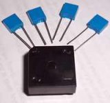
Something different goes on the diode bridge:
(Mark Houston's photograph)
See the right hand side of this photo.

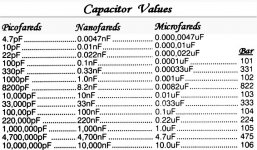
Those are Ten Nanofareds
Notice that they are printed with "103" and do please click the attached photo (below) so you can print out the capacitor values chart.
You may omit the caps from the diode bridge.
Term: "Diode Bridge" = Bridge Rectifier
P.S. Thanks for the "workout." That tells me that I should probably eliminate (omit) the 10nF caps from my beginner's power supply thread--the number ten is on the rectifier and the number one-hundred is on the power supply board, and they're getting confused. Please don't take offense. I'm very grateful to have this information.
EDIT: OH!! I see how this happened! My power supply photo doesn't specify which end is input or output (although it does show a rectifier). Will fix!
Attachments

danielwritesbac said:One resistor per rail, and 2 rails, means that the total number of resistors is 2.
That is a very slight added noise, so I think it goes close to the other noise--the rectifier.
The noise of the resistor is totally swapped by the overall low impedance of the power supply. I suggest you read up on noise theory....
So, was the 1/2w of 2.2k resistors within workable specs? I was aiming for a lighter than usual, but still workable, value. I've got some on my TDA7294 and they've never turned brown.
Yes, 2.2k 1/2W is fine up to about 40 volts. It will get hot on higher voltages.
]danielwritesbac said:
In my opinion, that answer is "no."
Nordic gave us the maximum figure of 22nF for use at the diode bridge--so 100nF is too big.
You can use (recycle) a pair of those 100nF at the opposite end, the "output" end, of the power supply (just one per rail), but they're not for use at the diode bridge.
Something different goes on the diode bridge:
(Mark Houston's photograph)
See the right hand side of this photo.
Those are Ten Nanofareds
Notice that they are printed with "103" and do please click the attached photo (below) so you can print out the capacitor values chart.
You may omit the caps from the diode bridge.
Term: "Diode Bridge" = Bridge Rectifier
P.S. Thanks for the "workout." That tells me that I should probably eliminate (omit) the 10nF caps from my beginner's power supply thread--the number ten is on the rectifier and the number one-hundred is on the power supply board, and they're getting confused. Please don't take offense. I'm very grateful to have this information.
EDIT: OH!! I see how this happened! My power supply photo doesn't specify which end is input or output (although it does show a rectifier). Will fix!
@daniel
btw i already finish my first power supply.
the power show as:
AC : 21 - 0 - 21
DC : 28.8 - 0 - 28.8
that is right?
btw my friend hand over this transformer but i don't know what ampere this transformer? can u guess for me?
thx u so much
156.34Asneih said:I don't know what ampere this transformer? can you guess for me?
Who wins the sweepstake?
Sneih, you may get a rough idea of the VA of your transformer by weighing it and comparing it to a list of different transformers (with the same voltages) for sale at somewhere like Farnell.
AndrewT said:156.34A
Who wins the sweepstake?
MJL21193 said:
My educated estimate is 156.32A.

sorry forget to attached picture...
hehe
glennb said:
Bleeder resistors
P = E * E / R
ie.
R = E * E * 2
eg. E = 30 volts, therefore R = 450 Ohms, or 470 Ohms for nearest preferred value of 1W resistor.
The bleed-off time is then 5 times t = R C
eg. for 22,000uF of caps,
Tdischarged = 5 * 470 * 22,000 * 10^-6 (convert uF to Farads)
= 51.7 seconds
what' meaning of 51.7seconds
can anybody help?
thx
sneih said:
what' meaning of 51.7seconds
Imagine a fully-charged capacitor value C farads connected in parallel with a resistor value R ohms; the capacitor discharges in an exponential decay curve such that after a time R x C seconds it's lost 63% of its charge
R x C is known as the 'time constant' of the circuit, symbol tau or 't' for ease, and if start =100V it's down to 37V after 1t, 13.7V after 2t, 5V after 3t, after 5t the capacitor has lost 99.9% of its charge and is effectively "flat".
Conversely, if you have an empty capacitor C charged through a resistor R the charge time follows an exponential curve such that the capacitor is 63% full after time R x C, 86.3% full after 2t, 95% full after 3t.
I should have just posted a link... 😱
what are the benefits of dual secondary vs CT vs dual transformer configuration, other than higher amps on the dual tranformer.
I use 24-0-24 CT standard transformer rated at 3A. it produce about +/- 32volts.
but a slight hum still audible if i stick my ears to the speaker. I already implement star ground configuration to the chipamp build.
or, maybe... just maybe, my mains doesnt have any earth connection. and maybe i should make an earth mains connection by sticking a 2meter copper rod to the ground.
Check if moveing transformers, affects the hum, make sure RCA jacks are isulated from the case, make sure high power wires are not next to signal wires etc...
The only difference between dual secondary and CT is that with the dual secondary the coil at the center tab is cut in two halves. By connecting the two wires you basically have the same configuration.
The advantage of dual secondary is that you can also parallel the secondaries to get the double current.
I see no advantage of dual transformer, it is tricky to set them in parallel, both transformers need to have the same specs. If you set them in series, also both transformers needs to have the same specs. Maybe this can have some advantage on the shape.
+/- 32V and you use the TDA2050?? This is way to high, this can cause the hum....
Regards, Rolf
The advantage of dual secondary is that you can also parallel the secondaries to get the double current.
I see no advantage of dual transformer, it is tricky to set them in parallel, both transformers need to have the same specs. If you set them in series, also both transformers needs to have the same specs. Maybe this can have some advantage on the shape.
+/- 32V and you use the TDA2050??
This is way to high, this can cause the hum.... Regards, Rolf
IceCube said:I see no advantage of dual transformer...
A probable advantage of the single transformer of double the VA is better regulation (a lower rise in voltage at low load).
As an example, for Clairtronic toroids my catalogue quotes regulation%:
- 30VA - 13.7%
- 50VA - 11.8%
- 100VA - 10%
- 160VA - 7%
- 300VA - 6.4%
- Status
- Not open for further replies.
- Home
- Amplifiers
- Chip Amps
- powersupply design question