sneih said:after see picture of post #1
what different of 100nf n 0.1uf?
thx
Well, there's no difference.
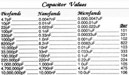
And, for extra fun, both are probably printed with "104" code number. See chart. (click picture).
Attachments
danielwritesbac said:Well, there's no difference.
And, for extra fun, both are probably printed with "104" code number. See chart. (click picture).
correct spelling is "Farad" --> http://en.wikipedia.org/wiki/Farad
Any easy way to remember the code is write down the first two digits, then write after it the number of zeroes given by the third digit. This gives the value in picofarads. Drop 3 of the zeroes to give nanofarads.
hm thx for simple tuts...
today i buy 8 caps (rubycon YXA 2200uF/35Volt) total= US$ 3
can i uses with 21v-0-21v transformer?
or i must reduces 18v-0-18v?
thx for answer!
today i buy 8 caps (rubycon YXA 2200uF/35Volt) total= US$ 3
can i uses with 21v-0-21v transformer?
or i must reduces 18v-0-18v?
thx for answer!
sneih said:hm thx for simple tuts...
today i buy 8 caps (rubycon YXA 2200uF/35Volt) total= US$ 3
can i uses with 21v-0-21v transformer?
or i must reduces 18v-0-18v?
thx for answer!
Yes you can use those caps with a 21-0-21 transformer. What are you powering ?
7/10
The 21 volt unit will certainly work fine for most applications.
Use of this spreadsheet
from National is VERY helpful for me.
good luck,
7/10
Use of this spreadsheet
from National is VERY helpful for me.
good luck,
7/10
sneih said:hm thx for simple tuts...
today i buy 8 caps (rubycon YXA 2200uF/35Volt) total= US$ 3
can i uses with 21v-0-21v transformer?
or i must reduces 18v-0-18v?
thx for answer!
21vac x 1.42 = 30vdc
This is "close" so use with a "snubbed" rectifier, like this one pictured (click picture below).
You can use 10nF polyester for the snubs, if you like. They'll take off the harshest of peaks, take off some noise and drop the voltage slightly. Subtracting the noise will help keep your big caps cooler and last long.
Attachments

At photograph #4 on this page:
http://diyaudioprojects.com/Chip/Synergy-LM3875-Gainclone/index.htm
Mark Houston shows the same snubbed rectifier.
http://diyaudioprojects.com/Chip/Synergy-LM3875-Gainclone/index.htm
Mark Houston shows the same snubbed rectifier.
yes, i make psu that u have attached at post#1danielwritesbac said:
21vac x 1.42 = 30vdc
This is "close" so use with a "snubbed" rectifier, like this one pictured (click picture below).
You can use 10nF polyester for the snubs, if you like. They'll take off the harshest of peaks, take off some noise and drop the voltage slightly. Subtracting the noise will help keep your big caps cooler and last long.
thx so much....
just to say thx for this spreadsheetseventenths said:The 21 volt unit will certainly work fine for most applications.
Use of this spreadsheet
from National is VERY helpful for me.
good luck,
7/10
Why bother with partially fixing a problem (turn off spikes on ordinary silicon rectifier diodes) which can be completely avoided.
Use schottky diodes or fast switching soft recovery (FSSR) diodes. Voila! No turn off spikes! Though these are harder to get hold of than ordinary diodes...
Use schottky diodes or fast switching soft recovery (FSSR) diodes. Voila! No turn off spikes! Though these are harder to get hold of than ordinary diodes...
21Vac will take the 35Vdc caps to near their specification limit.
I would recommend you measure the average DC voltage of the completed PSU with no load on the output (i.e. the supply rail fuses have been removed).
Now add on the ripple voltage to the average reading.
Now make an allowance for high mains supply voltage and calculate the maximum theoretical Vdc for max supply voltage.
The result must be below spec limit.
Theoretically this ripple + average is wrong, but some cap manufacturers specify this method of checking the operating voltage of their caps.
Ok, I've used 0,1 µF caps on each diode instead of 10 nF caps.
What is the worst that can happen?
What is the worst that can happen?
May I also add a pair of 1/2 watt 2.2k (or 2k) resistors?
Those would be great in parallel with the first two power caps (those that are closest to the rectifier).
Drainer / bleeder resistors are "slightly" helpful at a bit more level voltage.
So, then we have a snubbed rectifier, and its first two power caps (2200uF in this case) have 2.2k bleeder resistors. And, in this case, if those 35v caps outlast their first ten minutes, then they'll put in many years of service.
Don't connect the amplifier until after testing the power supply. That'll get the caps some time to break in gently. EDIT: Look up the light bulb-based testing tool.
ace7one said:Ok, I've used 0,1 µF caps on each diode instead of 10 nF caps.
What is the worst that can happen?
EDIT: There's no need to make the worst, because we have retail electronics stores for that.
Possible eye injury from an exploding cap is about the worst.
The runner up is weird frequency response abberations.
In third place, perhaps an awful smell that lasts for hours, along with a cloud of somewhat toxic materials.
For reference, 10nF = 0.01uF and they are printed with a "103" label on them.
From my observations and observed from a gentleman who actualy posted comparative scope traces... there is no real benefit going above 22nF..
Nordic said:From my observations and observed from a gentleman who actualy posted comparative scope traces... there is no real benefit going above 22nF..
sneih said:so complicated..........what's the true? 😀
Well, Nordic just did us the favor of stating the "large" size parameter. So, if you look closely, it seems that these capacitor values:
4.7 nanofareds or
10 nanofareds or
22 nanofareds or
anything between 4.7 nanofareds and 22 nanofareds
is the suitable size to snub a diode.
glennb said:Why bother with partially fixing a problem (turn off spikes on ordinary silicon rectifier diodes) which can be completely avoided.
Use schottky diodes or fast switching soft recovery (FSSR) diodes. Voila! No turn off spikes! Though these are harder to get hold of than ordinary diodes...
I'm after the clearly marked "+" and "-" on the plastic box versions of the 1 piece bridge rectifier. 😉
One of the square Kbpc1004 or Kbpc1005 is quite easy to snub for nice results with your center tap transformer.
-or-
Two of the "fork looking" Kbu1004 or Kbu1005 is fairly "explainable" for hooking up a dual-secondaries transformer. When reasonably placed side by side, presto! all of the connections become apparent. Then the 4 confusing wires of AC can get down to the necessary "V-, 0V, V+" for DC as simply as possible. I'm not going to snub that one.
danielwritesbac said:May I also add a pair of 1/2 watt 2.2k (or 2k) resistors?
Those would be great in parallel with the first two power caps (those that are closest to the rectifier).
Drainer / bleeder resistors are "slightly" helpful at a bit more level voltage.
Bleeder resistors do not do anything to improve the quality of the power supply, in fact they make the ripple slightly worse. Their only purpose in life is that when the mains power is turned off (and always unplug from the amp!), they make sure the reservoir / filter / bypass capacitors all drain to very near zero volts after some time (approx 5 "time constants", of t = R C). This is purely a safety measure so that DIYers don't get shocks or accidentally cause damage to the circuit while prodding around after the power has been turned off. It also makes it totally safe to disconnect / connect speakers and interconnects.
You really only need one resistor (per rail) and it can be put across any of the caps. Don't make it too low in value or it will just waste power that the transformer could otherwise deliver to the load (speaker). A rough rule of thumb is to use a 1W rated resistor and run it at 0.5 W, and then calculate its value as
P = E * E / R
ie.
R = E * E * 2
eg. E = 30 volts, therefore R = 450 Ohms, or 470 Ohms for nearest preferred value of 1W resistor.
The bleed-off time is then 5 times t = R C
eg. for 22,000uF of caps,
Tdischarged = 5 * 470 * 22,000 * 10^-6 (convert uF to Farads)
= 51.7 seconds
- Status
- Not open for further replies.
- Home
- Amplifiers
- Chip Amps
- powersupply design question