Hi,
But then, I tend to choose the cheapest toroidal transformers.
I have found that mechanical hum from the transformer can be worse as the VA rating goes up.DIY stuff with lavish margins on core size will be less affected
But then, I tend to choose the cheapest toroidal transformers.
AndrewT said:Hi,
post 1 in Poobah's link shows a very dangerous attempt at DC blocking. It is wired incorrectly. DO NOT copy post1

What is the reason of incorrect wiring?
Hi,
Believe me, do not copy post1! Yes, go and look and learn. Try comparing it to a correct wiring diagram. see post12.
lack of knowledge, working when fatigued, but maybe that was not the question.What is the reason of incorrect wiring
Believe me, do not copy post1! Yes, go and look and learn. Try comparing it to a correct wiring diagram. see post12.
AndrewT said:Hi, lack of knowledge, working when fatigued, but maybe that was not the question.
Believe me, do not copy post1! Yes, go and look and learn. Try comparing it to a correct wiring diagram. see post12.
Hi,
Sure, I believe you.
But, I do not hear from you about what is incorrect in wiring.
Could you give me a brief explanation?
Hi Dick,
You must know your normal working current. From that you can calculate the capacitor value to reach, but not exceed, your limiting voltage.
You then need to select capacitors that have sufficient ripple capacity.
You then need to select capacitors that can accept some reverse voltage.
You then need to select the correct voltage rating.
You then need to mount it so that technicians do not get electrocuted. You can never do enough to protect the idiot, some do exist.
Are you getting the message? Copy a known good circuit or go in with sufficient knowledge to design your own. But more importantly recognise when your knowledge may be lacking.
Working with mains voltage is DANGEROUS. Be armed with appropriate knowledge and experience before attempting any mains modifications or design.
BTW. I thinks it is Peranders that sells a kit to do DC blocking. His write up is extensive and correct, buy or copy.
No.Will most any electrolytic work in this application
You must know your normal working current. From that you can calculate the capacitor value to reach, but not exceed, your limiting voltage.
You then need to select capacitors that have sufficient ripple capacity.
You then need to select capacitors that can accept some reverse voltage.
You then need to select the correct voltage rating.
You then need to mount it so that technicians do not get electrocuted. You can never do enough to protect the idiot, some do exist.
Are you getting the message? Copy a known good circuit or go in with sufficient knowledge to design your own. But more importantly recognise when your knowledge may be lacking.
Working with mains voltage is DANGEROUS. Be armed with appropriate knowledge and experience before attempting any mains modifications or design.
BTW. I thinks it is Peranders that sells a kit to do DC blocking. His write up is extensive and correct, buy or copy.
Hi,
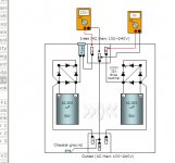
the layout is inherently dangerous. those single core, single insulated mains cables strung out across and along various routes is beyond bad practice.
The bridge is incorrectly connected.
The blocker is connected to both live and neutral.
No fuse.
No reference to safety earthing.
No warnings about mains working.
No instruction to the maintenance technician.
As I said
Try comparing it to a correct wiring diagram. see post12

Hi Bab,
do what you're told
do what you're told
Try comparing it to a correct wiring diagram. see post12
Hi AT,
I appreciate your safety concern very much as our profession here
is to verify and approve safety-related things. I really wanted
to discuss about the safety, but really disappointed. . .
I appreciate your safety concern very much as our profession here
is to verify and approve safety-related things. I really wanted
to discuss about the safety, but really disappointed. . .
Hi Bab,
your diagram is wrong!
You should not post mains related information if you cannot understand how to read a correct diagram.
As I said before, you should be able to recognise when your knowledge is lacking and seek help NOT post another wrong diagram.
Now print off the two diagrams (your one and the Bryston one) and compare the bridge connections.
Do what you are told and then we will not need to discuss it.
It will be obvious to you where the differences are.
AndrewT said:. . . your diagram is wrong!
. . . you cannot understand how to read a correct diagram.
. . . you should be able to recognise
. . . your knowledge is lacking
Is this your way of discussion?
OK, mine is the same as the one in post#3 (cap and diode arrangement).
Do you think post#3 is also wrong?
If you could indicate what was wrong, I could have been correct it.
🙄
Hi,
the circuit in post3 has been discussed at length.
I think most who took part in the discussion agreed that it kept the less safe practices of both camps without any of the benefits.
It seemed at the time that most were favouring keeping the DC block in the live line. A few, myself included, prefer to see the DC block in the neutral line.
The argument from both sides was that the risk of injury was increased by using the other variation.
Using the split two pole version (post3) as a balanced input held few if any additional benefits but kept the doubled risk of injury from having both lines DC blocked.
I think we were all agreed that post3 was the least safe, certainly I cannot recall anyone on the forum championing that layout.
A second problem your layout adopts is single diode voltage bypass.
The diodes may overheat in this situation. The diodes should only rarely be required to conduct, i.e. during start up or fault condition until protection triggers.
Running the diodes with repeated pulses was never intended, unless you are sure it will not cause an increased risk of failure.
How will you decide if there is increased risk of failure?
How will you test the long term reliability/safety of a prototype circuit?
Will the circuit achieve it's intended purpose, DC blocking, if the diodes repeatedly conduct?
Keeping in mind you/we are working with mains voltage, I recommend you scrap your layout and adopt a safer one.
Thnks for the schematic suggestions. I'm afraid they are far too complicated for me at this stage.
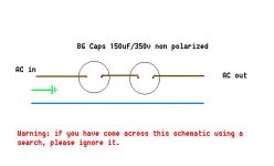
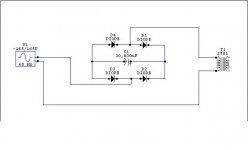
Going back to the Nelson Pass solution that I referenced to earlier, is that something like the schematic below? I happened to get some very cheap Black Gate NH 150uf/350v non-polarised caps, which are apparently useful for "pre-rectification filtering of AC". Would be nice if I could use them for something like this.....
( AndrewT, I appreciate your effort to give safety warnings and I have also read the moderator thread regarding dangerous schematics. With that in mind, I put a warning on the attachment in case any poor fool stumbles on it during a search. I must also repeat here that my electronics knowledge is still at the bottom of a very steep learning curve ).
Going back to the Nelson Pass solution that I referenced to earlier, is that something like the schematic below? I happened to get some very cheap Black Gate NH 150uf/350v non-polarised caps, which are apparently useful for "pre-rectification filtering of AC". Would be nice if I could use them for something like this.....
(
AndrewT, I appreciate your effort to give safety warnings and I have also read the moderator thread regarding dangerous schematics. With that in mind, I put a warning on the attachment in case any poor fool stumbles on it during a search. I must also repeat here that my electronics knowledge is still at the bottom of a very steep learning curve ).Attachments
Hi Ssmith,
your circuit has used poorly selected values.
A DC blocker neeeds to have a very low impedance to the normal AC current that passes to the toroid transformer.
Use the formula Impedance (Z)~= 1 / [2 Pi F C]
Your 150uF+150uF in series has an effectice capacitance of 75uF.
Assuming you have 50Hz mains supply then Z=42ohms.
If the limiting voltage drop across the DC blocker is 1Vrms (about 1.4Vpk) then the maximum operational current your 150uF can pass is 23mA (33mApk). If you have 220V mains supply then the maximum load is about 5watts.
Do your own numbers and you will find that 4700uF (4m7F) is about the minimum you can get away with. BUT you must ensure that the "ripple" rating of the cap exceeds the operational current.
How do you define operational current?
What are you planning for high current bypass?
What voltage caps do you need to specify?
What reverse voltage can be applied to a polarised electrolytic?
Why choose 1V as a limiting voltage?
What happens to your circuit if the amp develops an overcurrent fault?
This discussion could go on for ever. I'll stop and let you think about those decisions.
If you are not absolutely sure you can design this mains system then copy a known good design or buy one from Peranders.
Non polarised means you can pass AC through them without the need for back to back.
If you were to parallel the caps instead of series you can increase your maximum load to 20W.
AndrewT said:(...) I'll stop and let you think about those decisions.
Thank you for taking time out of your day to write all that. I'm thinking, I promise.
AndrewT said:If you were to parallel the caps instead of series you can increase your maximum load to 20W.
In other words, I'd need 6 in parallel for it to handle 60w....
AndrewT said:If you are not absolutely sure you can design this mains system then copy a known good design or buy one from Peranders.
...which is probably what I'll do while I try and take this all in...
Thanks again!
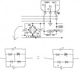
....here's something that Levinson used to do on the ML-9 (torroid), before they were absorbed by Harman. They called it "anti-rattle". As far as I know, it worked. I have no recollection of those mechanically humming/clacking. Maybe I just got lucky with cleaner power. It looks a bit like Babowana's, but it looks like his still has a danger of the caps getting reverse polarized. I've also heard of these referred to as a "coring" circuit. If anybody has any knowledge of that phrase, I would love to know more. Thanks
Attachments
Hi Ssmith,
Peranders circuit looks well designed and is supported by a good technical write up.
I have read hundreds of postings on DC blockers.
This apparently simple circuit is very poorly understood by most contributors in the DIYaudio Forum.
The mode of operation during different phases of start-up, normal running, fault current, and maintenance(tampering) must be fully understood before comtemplating a design and build. Although even normal operation is up for argument if you go and look at Eva's postings.
Whichever way you go take care.
Hi, Mrshow,
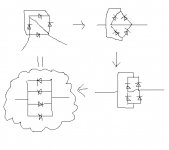
that circuit seems different again.
For current flow in each direction there is only one route from live to neutral through the cap.
That one route ensures the polarised cap never sees a reverse voltage.
The cap is in series with two forward biased diodes.
It forms an effective DC blocker.
BUT it has no bypass for high current!!! either start-up or fault.
If you were to design it for start-up current, I wonder just how much capacitance would be needed?
What would happen to it just before a fuse blew during an overcurrent fault?
- Status
- Not open for further replies.
- Home
- Amplifiers
- Power Supplies
- Powerline DC blocking and conditioning circuit