post219 shows some excellent work to try to find out what is happening.
That may lead to "why" it is happening.
This shows a big change in the inventor's apparent attitude.
Well Done. You are moving in the right direction. Stick to reporting facts and/or proposing hypotheses.
That may lead to "why" it is happening.
This shows a big change in the inventor's apparent attitude.
Well Done. You are moving in the right direction. Stick to reporting facts and/or proposing hypotheses.
My scopes all have a DC AC switch on each of the Y inputs.I get nothing meaningful to work with with scope set to DC
They display DC quite well.
Are your inputs capable of showing DC?
What's your point?
" but from what I am seeing on my scope at its settings of 2mv ac and 0.1us ( ........... ) there is benefit in loading the base with resistance, vs a short.
My scope shows what I assess as being a residual ( giving me a visual indication of something to work with ) at the above settings that improves its wave form as resistance is introduced from collector to base, the optimum being close to what I use with the op amp circuit. But there is a second result ... as the load is increased the wave form residual improves again. "
Chris, it is very difficult to understand what you are saying, and without knowing how your PSU, 'scope etc are connected and grounded this is all rather meaningless.
If you are getting a "residual" small AC waveform WITHOUT the op-amp being connected then it is coming from the PSU, or oscillating or airborne from something else.
How about drawing some diagrams showing how everything is connected? Verbal descriptions are much harder for engineers to follow!
For example, when connecting your 'scope to see this waveform where is the scope probe ground connected?
Is the scope also connected to mains safety ground?
When you have the op-amp connected, how are the power supplies connected to ground?
IME these details can often dominate small measurements and give rise to false or bizarre signals being observed.
My scopes all have a DC AC switch on each of the Y inputs.
They display DC quite well.
Are your inputs capable of showing DC?
What's your point?
I am guessing that on a 15V (ish) level it is not possible to see small changes with the Y amp at 5V/cm or similar.
AndrewT, Thanks I have amended websites, ( opera done& ebay in a few minutes from now ) awaiting better clarification on how to describe.
PSU is a LM338 Regulated variable supply 4700 uf cap prior, 100uf after. Vin 16v DC standard 35amp bridge package Vout 10v
and AndrewT and cliffforrest its 1.27am here so I will check my scope settings in the morning.. zzzz for now and reply then 🙂
Cheers / Chris
PSU is a LM338 Regulated variable supply 4700 uf cap prior, 100uf after. Vin 16v DC standard 35amp bridge package Vout 10v
and AndrewT and cliffforrest its 1.27am here so I will check my scope settings in the morning.. zzzz for now and reply then 🙂
Cheers / Chris
Last edited:
Ive never seen any that don't but not all have "auto-centering" or "trace finder" features. You can't assume that he is aware of this so he may just mean that there's nothing visible.My scopes all have a DC AC switch on each of the Y inputs.....They display DC quite well.
That's how I interpret it, he's looking at a small AC signal riding on a large DC signal.I am guessing that on a 15V (ish) level it is not possible to see small changes with the Y amp at 5V/cm or similar.
I do wonder about the horizontal at 0.1uS (per division). A 1MHz sine wave would fit the whole (10 division) screen, and any curve in the trace would indicate a signal over 100kHz.
Chris, if you can take a photograph of the scope display, that would also be very helpful.
I will take measurements DC and scope pictures from my Marantz CD80 today, I am placing an AD825 single on a small breadboard, connecting to a socket where I can then probe each channel, each audio output..transistor vs no transistor, this should then better qualify how the op amp is being used in a typical circuit. 🙂
Cheers / Chris
Cheers / Chris
I have modified an AD825 with short enameled wire leads for V+ and V- at the emitter connections following transistor , and small pins for V+ in and V- in so I can attach probe or DVM. Ground is the CD Players RCA socket.
Installed and playing a CD ( John Lee Hooker ) on a marantz CD80 AD825 op amp
Vin V+ is 16.16v+ Vout of Transistor Emitter is 15.47v+ C to E .696v
Vin V- is 15.62 V- in V- out transistor emitter 14.92V- C to E .701
I am currently researching a meaningful way ( following your advice AndrewT 🙂 ) for oscilloscope probe. When I describe nothing on DC settings I am just getting a flat line, adjusting axis for middle display. 5vdc 50ns prior to and emitter transistor- so nothing to report that would show any difference.prior or after. Some minor hash differences display at 2mv ac and 50ns that favor the transistor connection. Probing audio output is not likely to provide anything other than a complex music waveform, which would be common to transistor and non transistor op amps.. .
Crosstalk ( which I describe as better stereo - subjective finally meets measured without fighting ) is the key difference that I hear. So I am researching how crosstalk could be measured, Hmmmm not easy ...
Analog I note have a Spice model program for the AD825, I have had no success with National instruments Multisim program that returns Bad Format straight after downloading, however I may be able to access a CD from them, I am investigating GEDA as an alternative.... being GNU free software.
Cheers / Chris
Last edited:
LTspice is free, though not "open" - but is much better supported than geda spice
for spice sim many of us who can afford pro spice suites at work use LTspice
reported, verified bugs are fixed by Mike at Linear, often within a week or two - Linear engineers use the tool internally - and they are world class analog/mixed signal chip designers
for spice sim many of us who can afford pro spice suites at work use LTspice
reported, verified bugs are fixed by Mike at Linear, often within a week or two - Linear engineers use the tool internally - and they are world class analog/mixed signal chip designers
I will take measurements DC and scope pictures from my Marantz CD80 today, I am placing an AD825 single on a small breadboard, connecting to a socket where I can then probe each channel, each audio output..transistor vs no transistor, this should then better qualify how the op amp is being used in a typical circuit. 🙂
Cheers / Chris
How about playing some old mono CDs, and wire a speaker between the 2 live outputs of your power amp to get a difference signal.
How about playing some old mono CDs, and wire a speaker between the 2 live outputs of your power amp to get a difference signal.
I don't think it would be accurate enough.
Crosstalk within an amp, gain differences and gain differences with respect to frequency due to physical layout withinn the amp and crosstalk due to that would absolutely swamp what you were trying to measure.
I must admit though that Chris does keep mentioning channel separation as being so obviously improved and so it is worth using a test CD at 0db amplitude at 20khz with L and R channels separately recorded and then measuring the residual output on the other channel at the opamp output.
As CD players routinely better most amps on channel separation, and often by orders of magnitude I would be surprised if anything measurable showed up.
Consider also that vinyl had a channel separation of perhaps (from memory) 15 to 25 db ? at hf compared to CD at 90 to 100db............... so do the measurements 🙂
Great suggestion🙂, I have recorded 20Khz as Sine wave for 13 Mins as Flac using Audacity then burn't as audio using K3B, so will record as Land R channels separately, and measure residual on other channel ( the one not playing ) tomorrow.. relative to transistor vs non transistor op amp .
Thanks / Chris
Last edited:
I'm not sure we are talking of the same quality regarding channel separation here.
Earlier in the thread I recognised the description of a stereo image effect like that which is variously masked or enhanced by the amplifier's distortion when observed close to the speakers so as to hear detail. I don't hear it with class A amplification but it is readily observable in typical AB amplifiers and frequently referred to by reviewers when you read comments about the dimensions of the "sound stage" of a particular amplifier, player etc. Changing the amplifier shows different degrees and presentations of this so it's likely there are ways of repeating or increasing it in other circuits, maybe even by (ab)using op-amps.🙄
To me, it's not all hogwash but I don't think this separation effect has much to do with technically defined cross-talk.
I'm not sure we are talking of the same quality regarding channel separation here.
Earlier in the thread I recognised the description of a stereo image effect like that which is variously masked or enhanced by the amplifier's distortion when observed close to the speakers so as to hear detail. I don't hear it with class A amplification but it is readily observable in typical AB amplifiers and frequently referred to by reviewers when you read comments about the dimensions of the "sound stage" of a particular amplifier, player etc. Changing the amplifier shows different degrees and presentations of this so it's likely there are ways of repeating or increasing it in other circuits, maybe even by (ab)using op-amps.🙄
To me, it's not all hogwash but I don't think this separation effect has much to do with technically defined cross-talk.
I quite agree, which is why I suggested using real music not sine waves for judging this difference signal.
Hi
The test ran a Left channel recording of 20Khz,followed by a Right channel recording of 20Khz sourced as a Flac file generated by the software program Audacity and made as a CD using K3B.
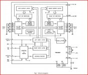
The TDA1541 is not a good candidate for this test at 20Khz, viewing the block diagram there is extra processing taking place within the DAC to enable the Right channel to exist, whereas the left gets straight access to pin " Data ". At 20Khz the Right channel is an identical copy of the Left.... which surprised me.
Whereas the Left appears where Channel separation is measured by Philips.
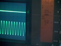
So Channel A in each case on my scope is the channel containing the opamp with transistors and Channel B is the channel without transistors, Both were AD825
In the first image which is Left 20khz The upper trace shows the output from the opamp not processing audio with transistors that can be seen contains no artifacts or disturbances 🙂, the lower trace is
the op amp without transistors processing 20khz.
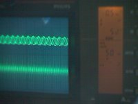
The second image shows the Right channel information that carries both channels imprinted on each other ( the inability of TDA 1541 to process Right channel at 20Khz )
and the lower trace contains lots of disturbance 🙁 being the channel not processing 20Khz and the op amp without transistors.
I would like to conduct this test on another CD player that processes Left and Right through its DAC more reliably
Cheers / Chris
The test ran a Left channel recording of 20Khz,followed by a Right channel recording of 20Khz sourced as a Flac file generated by the software program Audacity and made as a CD using K3B.
The TDA1541 is not a good candidate for this test at 20Khz, viewing the block diagram there is extra processing taking place within the DAC to enable the Right channel to exist, whereas the left gets straight access to pin " Data ". At 20Khz the Right channel is an identical copy of the Left.... which surprised me.
Whereas the Left appears where Channel separation is measured by Philips.
So Channel A in each case on my scope is the channel containing the opamp with transistors and Channel B is the channel without transistors, Both were AD825
In the first image which is Left 20khz The upper trace shows the output from the opamp not processing audio with transistors that can be seen contains no artifacts or disturbances 🙂, the lower trace is
the op amp without transistors processing 20khz.
The second image shows the Right channel information that carries both channels imprinted on each other ( the inability of TDA 1541 to process Right channel at 20Khz )
and the lower trace contains lots of disturbance 🙁 being the channel not processing 20Khz and the op amp without transistors.
I would like to conduct this test on another CD player that processes Left and Right through its DAC more reliably
Cheers / Chris
Attachments
Last edited:
Hi Chris,
Just trying to decipher what you have written but it appears something is going amiss somewhere... the two channels should process L and R information correctly.
Are you sure the file you burnt to disc is OK. Maybe repeat using say 10Khz just to see what is going on.
Not quite sure what you are looking at on the data sheet 🙂
If I have time later I might see if I can upload some audio test files (.wav)
as a bit of an experiment.
Attachments
As an experiment then... and .wav files were too large too attach so these are MP3 at 192khz sampling rate. These zip up to a very small file size, other bit rates and formats didn't. Which I don't understand why tbh 🙂
Not sure how these will turn out when unzipped and burned to CD-RW
Not sure how these will turn out when unzipped and burned to CD-RW
Attachments
The TDA1541 is not a good candidate for this test at 20Khz, viewing the block diagram there is extra processing taking place within the DAC to enable the Right channel to exist, whereas the left gets straight access to pin " Data ".
Sorry, but it's just you not being able to understand what the schematic says. The TDA1541 has been used for about 25 years and it is EXTREMELY unlikely no-one would have noticed this 'anomaly', don't you think?
Simply: read and UNDERSTAND the relevant paragraph where it ewplains what input formats for digital data the TDA1541 can work with.
The chip works just fine with each channel. If youa re getting the same thing on both with a 20kHz input signal on only one channel, then your DAC is faulty (or really badly done for that much cross-talk).
Also, why use a compressed format (FLAC) for the test when it's dead simple to use straight PCM? This just intorduces more places where things might go wrong. The first rule is always to simplify your measurment rig and eliminate everything that could confuse the interpretation of the results.
I would like to conduct this test on another CD player that processes Left and Right through its DAC more reliably
Why are you not splitting one output to the 2 opamp inputs to make sure the input signals are identical?
Last edited:
- Status
- Not open for further replies.
- Home
- Amplifiers
- Solid State
- Powering Opamps???