Hi,
The crux
The idea is to use an arduino controlled latching relay board. Main question, before going further choosing relays is... should power grounds be switched, or swithing the positive or negative wire/s is enough?
Background info
I'm designing an arduino controlled preamp. Power will be provided by an isolated DC-DC conversion board (taking power from a 12-24V) to LDO regulated 5V DC and ±12V DC. Besides de audio input selector (will be using maxw's board) I want to also be able to power unused circuits off. For instance, if I select audio coming from the NAS, I want to cut the ±12V DC power going to the phono amp off, and if I select the phono audio, I want to cut the 5V DC going to the RPi/DAC and the ±12V DC power going to the SE buffer after the DAC.
Thank you
EDITS:
1. Power switch as alternative to relays? post 20
2. Very basic drawing of PSU-Arduino-RPi connection post 32
3. NPN transistor driver for P-Channel MOSFET post 36
Attachments

Last edited:
In many cases the ground is also the reference level for the signal.
If you cut the ground connection to the power, the signal lead(s) will be pulled up by the circuit direction positive power.If that's no problem, go ahead !
Mona
If you cut the ground connection to the power, the signal lead(s) will be pulled up by the circuit direction positive power.If that's no problem, go ahead !
Mona
There might in some circumstances be safety issues switching ground - keeping grounds bonded reliably seems a very desirable aim. Besides most relays are limited to DPDT contacts which is only enough to switch +/- rails. Three or four pole latching relays are probably more difficult to source.
Switching positive and negative (where applicable) supplies is enough to get things switched off properly. Also switching grounds usually causes more problems than it solves; there might be cases where it helps to prevent ground loops, but it also means that the potential differences between the different circuits can become totally uncontrolled.
And, if it is small-signal cirquits (preamp, etc) - I'm not sure that there is a need to switch power lines. Usually signal wires are switched only.
We switch off usually only larger power devices, like power amplifier.
We switch off usually only larger power devices, like power amplifier.
Thank you all
Thank you again everyone.
Sorry Mona, didn't quite understand.In many cases the ground is also the reference level for the signal.
If you cut the ground connection to the power, the signal lead(s) will be pulled up by the circuit direction positive power.If that's no problem, go ahead !
Mona
My power grounds will actually be isolated due to the isolated DC-DC before the relays board. Another option would be having the relays before the DC-DC conversions, in that case all grounds would be the same.There might in some circumstances be safety issues switching ground - keeping grounds bonded reliably seems a very desirable aim.
Yes, that ¡s another story. They exist but are scarce and more expensive... But, shouldn't it be SPSP to switch 5V, and DPST to switch ±12V?Besides most relays are limited to DPDT contacts which is only enough to switch +/- rails. Three or four pole latching relays are probably more difficult to source.
Usually there is no need to switch ground (it's may be even worse).
Cool then. I'll simplify.Switching positive and negative (where applicable) supplies is enough to get things switched off properly.
OK. I'm going to use isolated rails, but I suppose that's still possible.Also switching grounds usually causes more problems than it solves; there might be cases where it helps to prevent ground loops, but it also means that the potential differences between the different circuits can become totally uncontrolled.
That's a good point, but I'm going to use DC power (avoiding AC mains completely). In this scenario, I think trying to avoid over-dimensioning the initial DC source and also avoid wasted unused power makes sense.And, if it is small-signal cirquits (preamp, etc) - I'm not sure that there is a need to switch power lines. Usually signal wires are switched only.
We switch off usually only larger power devices, like power amplifier.
Thank you again everyone.
It would be good to calc "power budget". For example, if you use relays - it may be that relays itself consume more than small-signal cirquits tbat you want to switch off.In this scenario, I think trying to avoid over-dimensioning the initial DC source and also avoid wasted unused power makes sense.
If I’m not mistaken, one of the advantages of latching relays is that they only consume power when switching takes place?It would be good to calc "power budget". For example, if you use relays - it may be that relays itself consume more than small-signal cirquits tbat you want to switch off.
I want to also be able to power unused circuits off.
And the reason for this complication is? Just to please Greta? 😀
Why use relays instead of mosfets?
Yes.If I’m not mistaken, one of the advantages of latching relays is that they only consume power when switching takes place?
Hi,
As for:
I don’t know how that would work, sorry for my ignorance. Also, would that approach allow the Arduino to manage the timing of those on/offs?
Thank you
I don’t know who that Greta is, but reasons explained in first and 7th post, more specificallyAnd the reason for this complication is? Just to please Greta? 😀
I'm going to use DC power (avoiding AC mains completely). In this scenario, I think trying to avoid over-dimensioning the initial DC source and also avoid wasted unused power makes sense.
As for:
Why use relays instead of mosfets?
I don’t know how that would work, sorry for my ignorance. Also, would that approach allow the Arduino to manage the timing of those on/offs?
Thank you
Suitable mosfets are better than relays in the ON position and worse in the OFF. Don't make clicks, don't age, easy to control multiple switches.
Hi, I don’t know who that Greta is, but reasons explained in first and 7th post, more specifically
Read the 7th post. Looks like you do know Greta after all 😛
Have you calculated the savings? Does it amount to whole milliwatts or just fractions?
Still, would that approach allow the Arduino to manage the timing of those on/offs?Suitable mosfets are better than relays in the ON position and worse in the OFF. Don't make clicks, don't age, easy to control multiple switches.
If you say soRead the 7th post. Looks like you do know Greta after all 😛
Savings around full watts, yes. Phono amp can probably consume 0,25W per channel, but the RPi will consume 10W (5V@2A) if using display, etc.Have you calculated the savings? Does it amount to whole milliwatts or just fractions?
unless your chip draws alot, don't bother. I'm using an MKR1010 and it draws maybe 50ma. The I2C and logic draws almost nothing while in standby (not being accessed mode)
latching relays only draw while changing state. you will have to program in a latching pulse for both the "on" and "off" states of the relays.
I used CD4052 cmos switches for analog inputs on an old car stereo that is still a great sounding unit. I also used CD4066 for a stereo 1024 step volume control back in 85 or 86 that still outperforms most volume pots.
Last edited:
Phono amp can probably consume 0,25W per channel
Damn. one of my tube phono stages uses almost 80W from the wall! 10 tubes, 2 for voltage regulation, all running from 12V with boost converters.
It's not the MCU that worries me (Arduino consumes much less, but it also will be on all the time). The problem is the RPi, which consumes quite a lot more and it needs software/logic to power off gracefully.unless your chip draws alot, don't bother. I'm using an MKR1010 and it draws maybe 50ma. The I2C and logic draws almost nothing while in standby (not being accessed mode)
cool, that was the main idealatching relays only draw while changing state. you will have to program in a latching pulse for both the "on" and "off" states of the relays.
mmm will have to look for it, but I don't think/remember CMOS switches for 4A. For instance, CD4052 & CD4066 DS state "DC input current ±10mA". If there are other chips with higher input current tolerance, then it'd be a fantastic solution, yes, since I don't care too much for the audio signal quality here, we're talking about power rails. Will do my homework, thank you.I used CD4052 cmos switches for analog inputs on an old car stereo that is still a great sounding unit. I also used CD4066 for a stereo 1024 step volume control back in 85 or 86 that still outperforms most volume pots.
Yup, but this is op-amp based, completely different approaches.Damn. one of my tube phono stages uses almost 80W from the wall! 10 tubes, 2 for voltage regulation, all running from 12V with boost converters.
Thank you again, everyone
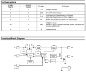
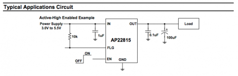
I might've found a way to avoid relays, using a power switch per each optional rail, at least for the 5V@3A. For instance, AP22815BWT-7. If I'm not mistaken this chip accepts a Input Voltage Range of 3.0V ~ 5.5V, and has an Enable input that acts as the switcher. It even has Overcurrent, Short-Circuit and Thermal Protection, Output Reverse-Voltage/Current Protection, Undervoltage Lockout etc. The EN feature is described as:
Would anyone here please confirm this is a valid approach or I'm completely nuts? If this is valid, I'd need to find a similar product for +12V and for -12V rails.
Thank you so much
ON/OFF Input Operator
The EN input allows the output current to be switched on and off using a GPIO compatible input. The high signal (switch on) must be at least 1.2V and the low signal (switch off) no higher than 0.4V. This pin should not be left floating. It is advisable to hold the EN signal low when applying or removing power
Would anyone here please confirm this is a valid approach or I'm completely nuts? If this is valid, I'd need to find a similar product for +12V and for -12V rails.
Thank you so much
Attachments
- Home
- Amplifiers
- Power Supplies
- Power unused circuits off: should power grounds be switched?