Just today I was thinking about my future amp project, a 45 direct coupled SE. Recently I found that diode biasing a triode (6C45's in a RIAA preamp) can be a nice thing. In the case of the 45, it would save a lot of money and inside space in the chassis, what with the size of large bypass film caps (I use Solen Fast).
So why not do it with a vacuum diode? A rectifier comes to mind - there are a number of relatively cheap rectifiers able to push thru the needed 40mA of current.
What do you think, is this smart? Can it be done?
So why not do it with a vacuum diode? A rectifier comes to mind - there are a number of relatively cheap rectifiers able to push thru the needed 40mA of current.
What do you think, is this smart? Can it be done?
Attachments

Look at the V vs I curve for a 6X5, for example. The AC impedance is dV/dI, which looks like 250-300 ohms for that tube. Other high vacuum rectifiers are similar.
Like SY said, impedance is a bear on most vaccuum diodes. I've experimented with it a little, somewhat promising results, as long as your diode drops the necessary voltage at the desired current. Finding a pair of diodes reasonably matched is the main issue. I wouldn't do it for SE, due to voltage drops changing during current peaks. On a PP amplifier it seems like it may be promising, although either way your basically using it like a hot resistor though. I dropped my experimenting and just started tinkering around with LED arrays instead. VR tubes however...
I'm afraid I still don't understand what the problem would be? Please elaborate.
I've understood that class A circuits always draw the same current, so why would there be current peaks?
I've understood that class A circuits always draw the same current, so why would there be current peaks?
You mean that a vacuum diode wouldn't prevent regenerative feedback? Ah. Feeling a bit slow right now.
So I guess I'm stuck with solid state diodes or larger than life film caps.
Well, thanks for clearing this up.
Well, thanks for clearing this up.
So I guess I'm stuck with solid state diodes or larger than life film caps.
Not necessary. P-type source follower may work as well.
Why not put the bias on the grid, where it belongs?
Needs to be adjusted. So, people use self-bias in class A amps to avoid adjustments. However, it greatly increases output resistance, so people shunt cathode resistor by capacitor. When they don't like capacitors they search for something with less dynamic resistance. Gradually they are coming to P-type source follower, or PNP emitter follower, fed by voltage adjusted by a trimpot. Now, to close the circle it is logical to go back to grid bias by a trimpot.
But what if you want to avoid interstage coupling capacitor? You still need something in cathode... I've proposed once an optimal solution: to load a driver stage on CCS controlled by sensor of cathode current of output tube. Can be very elegant, if properly implemented.
http://www.chimeralabs.com/images/axiom.sch.jpg
It uses damper diodes.
Large/old style of 'Red light zone' ? 😆
Interesting circuit, though.
It uses damper diodes.
Large/old style of 'Red light zone' ? 😆
Interesting circuit, though.
I've proposed once an optimal solution: to load a driver stage on CCS controlled by sensor of cathode current of output tube. Can be very elegant, if properly implemented.
Nice solution indeed. Would it not require negative supply rail as well?
Nice solution indeed. Would it not require negative supply rail as well?
Absolutely not necessary!
nice.
Sure, if you lift cathode 150V up 🙂 . But Q3 is dissipating about 15W now. I was thinking more like a small sense resistor in cathode path -> servo amp -> CCS load for driver controlled by servo amp generated voltage.
Sure, if you lift cathode 150V up 🙂 . But Q3 is dissipating about 15W now. I was thinking more like a small sense resistor in cathode path -> servo amp -> CCS load for driver controlled by servo amp generated voltage.
nice.
Sure, if you lift cathode 150V up 🙂 . But Q3 is dissipating about 15W now. I was thinking more like a small sense resistor in cathode path -> servo amp -> CCS load for driver controlled by servo amp generated voltage.
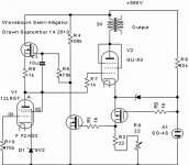
Yes, like it was originally in Alligator.
10 Ohm cathode resistor was used both to adjust bias of an output tube, and supplied reference voltage to the current source that pulled down another side of an output transformer.
- Status
- Not open for further replies.
- Home
- Amplifiers
- Tubes / Valves
- Power triode bias by tube rectifier