a power traffo with a secondary winding that have adjacent turns short will blow the fuse, so i am a bit confused as to what your problem really is...
Ok, here we go again.
1) this is not a "tube" amp but an SS one, with some tube flakes sprinkled on top to add flavour.
Meaning: it is a 95% SS oriented power transformer, with a minimal Tube type job.
2) comparing original and "after" pictures tells me that:
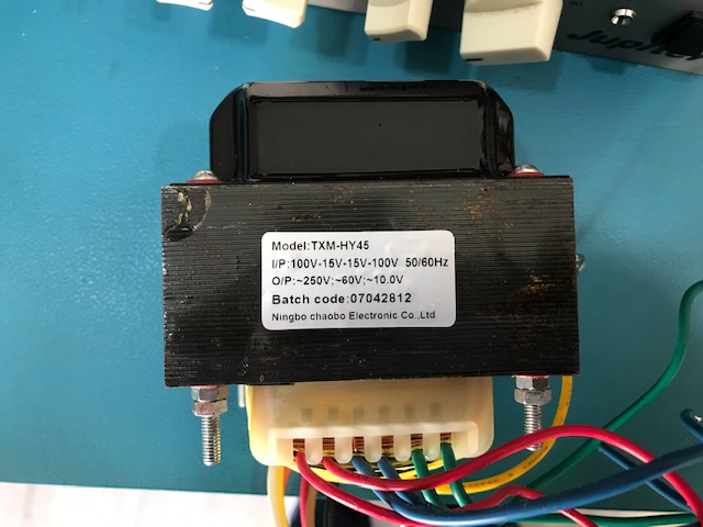
Laminations were removed: lost black paint, now are painted with insulating varnish. Plus label is mangled, almost broken.
That said:
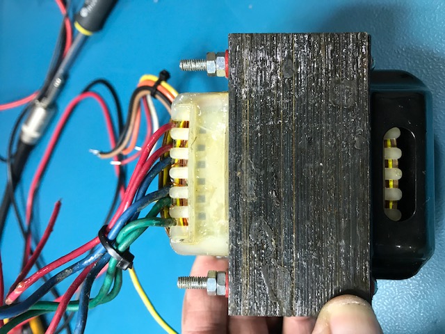
* bobbin/winding looks untouched
* brown varnished insulated paper may have been replaced.
3) yet I think it was not rewound for the very good reason it´s a complex multi primary and secondary winding transformer, at least 6 independent ones (2 wires per winding) but maybe more if some of the wires lead to centertaps, in such case 3 wires mean 2 series connected windings.
Main problem being that each winding uses a different diameter wire which not only requires a different supply spool (duh!!!) but more important: resetting winding machine to a new advane pitch (which equals effective wire diameter).
My point being it´s slow and annoying.
No big deal at Factory because you set advance for, say, 0.12mm wire, do whatever winding needs it, on a large batch, say 50/100/1000 units, whatever the order is; then set it to, say, 0.25 mm, wind the whole batch, and so on.
Justified on an OEM order, a PITA for a single one.
And to boot they did not charge for that?
And they are supposed to have done that twice?
IMPOSSIBLE.
3) so my take is that they have not rewound it but just removed brown paper and resoldered a poor connection ... which still fails.
Enamelled wire is insulated by definition and unsolderable, so usually its end is burnt and lightly sanded to expose shiny copper, then soldered to output PVC insulated cables.
If done improperly (enamel ash not properly removed or surface is dirty) molten solder does not actually alloy with copper but simply solidifies around it.
What´s improperly called a "cold solder" but actually much worse.
Applying a hot soldering iron tip to a cold solder will repair it, applied to dirty wire it will not and that´s what I suspect.
I guess both times they did just that; it worked, sort of, but unreliably and will fail again, over and over.
The rest of the transformer seems to work well, so I suggest you use it as is , and add an extra 250V supply for the tube plates.
4) let´s first see what you have:
Primaries: 100 - 15 - 15 - 100 VAC
Allow any mains voltage from 100 - 115 - 130 - 215 - 230 VAC mains, anywhere on the World.
So far so good.
Secondaries:
* 250VAC for tube HT <--- this one is failing
* 60VAC compatible with an SS amplifier.
Might mean 80V single supply (capacitor output) or if center tapped 40+40V rails. Seems to be working properly.
* 10VAC.
May be rectified to feed 12.6VDC filaments (or series connected 6.3V ones) and down regulated to 5V to feed the Belton brick digital reverb .
It can also supply some +/-14V to feed the visible relay and Op Amp.
Since most works, except the iffy 250VAC, as a practical solution I suggest you add a small 220/240V to 9VAC transformer inside that chassis, connected backwards so 9V winding gets nominal 10VAC and its primary supplies the HT or, if you want to play it safe, a 220/240V to 12VAC one.
You will get a somewhat reduced "250VAC", probably closer to 200VAC ... which is no problem at all.
Get the smallest one, 250mA is ample, even 100mA if you can find it, chassis is full but you can bolt it to the opposite side, 2 small bolts going through the aluminum plate heatsink won´t affect it.
And drill a small hole (8-10mm) for wires to go through it.
1) this is not a "tube" amp but an SS one, with some tube flakes sprinkled on top to add flavour.
Meaning: it is a 95% SS oriented power transformer, with a minimal Tube type job.
2) comparing original and "after" pictures tells me that:
Laminations were removed: lost black paint, now are painted with insulating varnish. Plus label is mangled, almost broken.
That said:
* bobbin/winding looks untouched
* brown varnished insulated paper may have been replaced.
3) yet I think it was not rewound for the very good reason it´s a complex multi primary and secondary winding transformer, at least 6 independent ones (2 wires per winding) but maybe more if some of the wires lead to centertaps, in such case 3 wires mean 2 series connected windings.
Main problem being that each winding uses a different diameter wire which not only requires a different supply spool (duh!!!) but more important: resetting winding machine to a new advane pitch (which equals effective wire diameter).
My point being it´s slow and annoying.
No big deal at Factory because you set advance for, say, 0.12mm wire, do whatever winding needs it, on a large batch, say 50/100/1000 units, whatever the order is; then set it to, say, 0.25 mm, wind the whole batch, and so on.
Justified on an OEM order, a PITA for a single one.
And to boot they did not charge for that?
And they are supposed to have done that twice?
IMPOSSIBLE.
3) so my take is that they have not rewound it but just removed brown paper and resoldered a poor connection ... which still fails.
Enamelled wire is insulated by definition and unsolderable, so usually its end is burnt and lightly sanded to expose shiny copper, then soldered to output PVC insulated cables.
If done improperly (enamel ash not properly removed or surface is dirty) molten solder does not actually alloy with copper but simply solidifies around it.
What´s improperly called a "cold solder" but actually much worse.
Applying a hot soldering iron tip to a cold solder will repair it, applied to dirty wire it will not and that´s what I suspect.
I guess both times they did just that; it worked, sort of, but unreliably and will fail again, over and over.
The rest of the transformer seems to work well, so I suggest you use it as is , and add an extra 250V supply for the tube plates.
4) let´s first see what you have:
Primaries: 100 - 15 - 15 - 100 VAC
Allow any mains voltage from 100 - 115 - 130 - 215 - 230 VAC mains, anywhere on the World.
So far so good.
Secondaries:
* 250VAC for tube HT <--- this one is failing
* 60VAC compatible with an SS amplifier.
Might mean 80V single supply (capacitor output) or if center tapped 40+40V rails. Seems to be working properly.
* 10VAC.
May be rectified to feed 12.6VDC filaments (or series connected 6.3V ones) and down regulated to 5V to feed the Belton brick digital reverb .
It can also supply some +/-14V to feed the visible relay and Op Amp.
Since most works, except the iffy 250VAC, as a practical solution I suggest you add a small 220/240V to 9VAC transformer inside that chassis, connected backwards so 9V winding gets nominal 10VAC and its primary supplies the HT or, if you want to play it safe, a 220/240V to 12VAC one.
You will get a somewhat reduced "250VAC", probably closer to 200VAC ... which is no problem at all.
Get the smallest one, 250mA is ample, even 100mA if you can find it, chassis is full but you can bolt it to the opposite side, 2 small bolts going through the aluminum plate heatsink won´t affect it.
And drill a small hole (8-10mm) for wires to go through it.
a power traffo with a secondary winding that have adjacent turns short will blow the fuse, so i am a bit confused as to what your problem really is...
Depends on the shorted windings' cross section, I'd say .
Best regards!
No shorted winding here.
A "small unimportant" shorted winding is still a short across the magnetic core.
Thin wire highish resistance may prevent its blowing mains fuse but it will heat up by itself until molten or catching fire, not the case here.
I bet Osvaldo´s suggestion (*actually* measuring wire resistance instead of repeating textbook lines) would have shown this.
Like Enzo says: "make no excuse for NOT checking something" 😉
FWIW the OP never answered my question about supply capacitor values , which could have shed some light on this.
Without that, I had to assume a lot. (my supply voltages analysis).
Last edited:
250VAC for tube HT <--- this one is failing
i suspect a faulty filter capacitor that pulled down the voltage, the 500 ohm dc resistance for that winding made for the very low voltage.
i suspect a faulty filter capacitor that pulled down the voltage, the 500 ohm dc resistance for that winding made for the very low voltage.
Not impossible but, say, 200V dropped across 500 ohms (since measured output is around 50V and rated one is 250V) means a small winding made out of VERY THIN wire (to account for 500 ohm DCR) makes it dissipate 80W continuously 😱
Such power on a small winding (hey, it would be too much even for the thick wire 60V one) will overheat, toast and burn or melt it in a few minutes.
I maintain my open-poor contact theory which is not catastrophic compared to the shorted winding one, and suggest leaving it alone (open/unterminated windings do not hurt power transformers) , instead generating HV from another source.
I suggest a small reverse transformer (Marshall Valvestate amps use the same trick) but of course any of those high voltage small inverters running out of rectified 12-14V DC can do a similar job.
Just avoid coupling switching noise into the Audio signal.
that is why this thread is confusing, lot's of loose ends, if i have the thing in front of me, then things will be surely different...
FWIW the OP never answered my question about supply capacitor values , which could have shed some light on this.
Im sorry to miss that, but your analysis is correct.
Since most works, except the iffy 250VAC, as a practical solution I suggest you add a small 220/240V to 9VAC transformer inside that chassis, connected backwards so 9V winding gets nominal 10VAC and its primary supplies the HT or, if you want to play it safe, a 220/240V to 12VAC one.
You will get a somewhat reduced "250VAC", probably closer to 200VAC ... which is no problem at all.
Get the smallest one, 250mA is ample, even 100mA if you can find it, chassis is full but you can bolt it to the opposite side, 2 small bolts going through the aluminum plate heatsink won´t affect it.
I think im going to do that. Thats a great idea. At least gives me the chance to make sure the circuit is performing well.
Yes, of course, you *may* have bad filter caps too.
At least on the HV rail.
Just curious: o senhor é Brasileiro?
At least on the HV rail.
Just curious: o senhor é Brasileiro?
the 12ax7's even if you have 4 plates will not consume more than 6mA, there is more power consumed at the filaments, 12vdc x 350mA or 4.2 watts..
- Home
- Amplifiers
- Tubes / Valves
- Power transformer