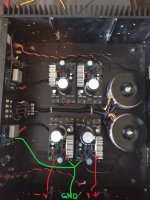
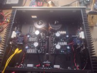
It is somewhat unusual to hook up positive to GND and errors with consequences can be made so being cautious is good. The point of course is that the normally negative side is now not connected to GND. Feels strange, is strange, should be treated as strange but works perfectly 🙂
In this hobby you will notice many to dislike this way of regulating (despite that nothing is wrong) and prefer to use "real" negative regulators instead.
In this hobby you will notice many to dislike this way of regulating (despite that nothing is wrong) and prefer to use "real" negative regulators instead.
Last edited:
We are just not used to connect separate supplies like that. But, there is no performance difference compared to pairing one 'positive' and one 'negative' supply.
How do we connect the same polarity batteries to get symmetrical supplies? 😉
How do we connect the same polarity batteries to get symmetrical supplies? 😉
With batteries this is fully normal in power electronics but still spectacular errors can be made. Also with batteries in series and a + and - 400V branch taking out one battery in the middle of either string can be very dangerous in a few nasty ways. One needs to triple check and overthink actions before doing anything. Most electrical brains are not trained to think of both a positive and a negative branch and potential differences in a few ways simultaneously (is my assumption/explanation).
It is probably strong emotion based on first experiences long ago when shorting stuff as practically every seasoned DIYer feels it. I recently sold a PSU that was constructed like this as I refused to use it in my device. Nonsense, I know.
It is probably strong emotion based on first experiences long ago when shorting stuff as practically every seasoned DIYer feels it. I recently sold a PSU that was constructed like this as I refused to use it in my device. Nonsense, I know.
Last edited:
A song for you: 😆I recently sold a PSU that was constructed like this as I refused to use it in my device. Nonsense, I know.
Last edited:
You are right but IMHO the chance of making mistakes when using “real” negative regulators is lower. Well maybe not opinion but more a fact. It is a mirror of the other circuit with GND being GND for both and not an identical copy of the positive regulator connected “wrong”.
Wow, technical preferences based on emotions. Novelty 😉
Wow, technical preferences based on emotions. Novelty 😉
Last edited:
I have completed the build and I thought I saw somewhere in the thread a startup procedure and now that I would like to see it I can't locate it.
Post 29 by Tombo basically gets you going. When my amplifier first starts, all the boards have a red light on, then slowly they start to go out. During this time you can hear a hum at the speaker. Once they goto green light everything is quiet. I was only able to get 22.5 volts under load with dual 160va transformers and 18v secondaries.
Very good method of checking built R25 supply is by using some bench variable power supply. They can be connected to the R25 input with no consideration for polarity, as there is a rectifier at the R25 input anyway. Using usually available current limiting at those bench supplies is a very convenient safety measure.
Start with 15V and no load. If regulator behaves, you can continue with required voltage and load. Under load, take care that voltage drop across regulator is not high if load current is high as well.
Voltage drop under operating conditions (@gsrchrisu - especially if regulators are inside amplifier case 🙂) can be easily measured by connecting voltmeter between points marked on the attached picture. Q1 metal tab has direct connection to the positive pole of the reservoir capacitor.
As mentioned many times, due ripple voltage and mains voltage variation, in case of class A amplifiers, operating voltage drop should be about 1 – 1.5 V. It can be lower but you have to check that during max. mains load in your area, input voltage doesn’t go too low.
For class AB, regulators should operate between 3 – 5V voltage headroom at the amplifier’s idle state. Depends on transformer quality and how much will C2 voltage drop under full load.
Attachments
- Home
- Amplifiers
- Power Supplies
- Power Supply with Active Rectifier, RF Filter and Super-Regulator
 Posts removed following the banning of a sockpuppet account.

