Hi,
have you got decoupling caps on the supply pins of the opamp?
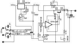
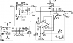
Have you fitted the recommended bypass caps to the input and output pins of the 317?
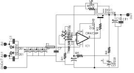
The output voltage measuring resistors 2k4 & 1k2 set up 5V on inverting input from 15V on output.
What voltage is showing on the output of the opamp?
and on the base of the 340?
and on the output?
and on the 340 collector?
How much current does the 329 need? Only 2mA is flowing through 5k1.
have you got decoupling caps on the supply pins of the opamp?
Have you fitted the recommended bypass caps to the input and output pins of the 317?
The output voltage measuring resistors 2k4 & 1k2 set up 5V on inverting input from 15V on output.
What voltage is showing on the output of the opamp?
and on the base of the 340?
and on the output?
and on the 340 collector?
How much current does the 329 need? Only 2mA is flowing through 5k1.
Hi Andrew T,
no i don't decoupling the supply pin on opamp. i will test this weekend. But if i disconnect the 340 collector, the 317 is ok.
For my output voltage i setting for 21Volt( (2.4K+1.2K)*6.9Vref/1.2K. For my circuit voltages are:
opamp
pin2 and 3: 0.3 and 0.7v
pin6: 1.4v
pin7: 27v
mje340
base: 1.5v
emit: 0.9v
coll: 27v
Thank You!
Hi,
are the pin outs of the 134 the same as 817?
The voltage difference pin2 to pin3 should be near zero. The large differential voltage is trying to force the output high but your's is still reading too low, the base of 340 appears to be pulling too much current. Could the 134 be current limiting?
Second problem;- pin 3 should have reference voltage. It is showing only 0.7V, where are the lost 200mV? Could the 47uF/328 be shorted/faulty?
Alternatively can you temporarily connect 328 to 340 collector with your 5k1? so that you feed a true reference to non-inverting pin. Then remeasure your voltages.
Hi,
yes the pins out are the same. I have the problem only when the diodes are connected. I tested or changed my components lm329, caps and ic. If i remove the diodes 1n4148 my circuit is ok, it oscillates but the voltage it is at 21V. Why when i connect my diodes the voltage drop? thank you!
maxpou
yes the pins out are the same. I have the problem only when the diodes are connected. I tested or changed my components lm329, caps and ic. If i remove the diodes 1n4148 my circuit is ok, it oscillates but the voltage it is at 21V. Why when i connect my diodes the voltage drop? thank you!
maxpou
jackinnj said:
That fateful phrase from Audio Amateur "It oscillates, now what" --
Hi Jack,
Obviously I need to react on this!
Let me say that the reg as shown, with the board and layout as shown, and with the AD817 which I personally always use here does not oscillate. And starts up without problems.
But many unsuspecting builders make "improvements" like large-value film caps at the output that *can* make it oscillate. Therefore I put in that sidebar you mentioned, rather than just shutting up and silently wishing them good luck.
Hope this helps 😱
Jan Didden
Hi Jan Didden,
which cap can cause my problem and why when i place the diodes 1n4148 my voltage drop. thank You!
which cap can cause my problem and why when i place the diodes 1n4148 my voltage drop. thank You!
Hi,
if i don't place the diodes 1n4148 in the circuit my all voltage are O.K. but it oscillates at 110Khz. it's sure i want place the diodes for protection. thank you!!!
if i don't place the diodes 1n4148 in the circuit my all voltage are O.K. but it oscillates at 110Khz. it's sure i want place the diodes for protection. thank you!!!
Hi,
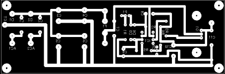
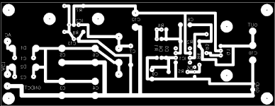
i found my problem. I removed the cap C11(0.01uf wima) see my pcb post 22 and it don't oscillates. but if i place the cap 0.01uf directly on C10 pins it don't oscillates. 😀 thank you for your helds!
i found my problem. I removed the cap C11(0.01uf wima) see my pcb post 22 and it don't oscillates. but if i place the cap 0.01uf directly on C10 pins it don't oscillates. 😀 thank you for your helds!
Hi,
that's what Eva keeps telling us and some (me included) don't want to believe it. Lesson learned.
Now that the oscillation has stopped, can you confirm that the diodes are performing correctly? And that the voltages around the circuit are back to normal?
I have gone back to compare your schematic post21 with PCB post22 . I cannot follow the route:- pin3-r5-r4-output. Are c10 & r4 labels misplaced?
Hi,
thank you Eva for your help! lesson learned me too.
Andrew but, the performance of the diodes is not correct. i have the same problem with my voltages arround the IC.
I posted a next time my new schematic and PCB. i labels of C10 is at left side of cap and for R4 is at right side of resistor.
thank you!
Hi,
I can see C10 label is left of the cap location pin pitch about 0.4inch.
I can see an R4 label to the right of two holes about 0.7inch pin pitch running top to bottom. Am I reading you correctly?
I can see C10 label is left of the cap location pin pitch about 0.4inch.
I can see an R4 label to the right of two holes about 0.7inch pin pitch running top to bottom. Am I reading you correctly?
Hi,
take your pin 4 power connection off the lower ground trace NOT off the sensitive pin 2 pin3 feedback trace.
The two connections that feed the bridge comparing the output conditions should have their own dedicated traces connected direct to the output pads and nothing else should be allowed to contaminate these feed back lines.
The bridge is formed by R2+R1 and R4+R5 with C8, C9 & D5.
- Status
- Not open for further replies.
- Home
- Amplifiers
- Power Supplies
- power supply sulzer-borbely