Build a Mains Bulb Tester.
C1 is in the wrong place.
As shown it bypasses the switch, so that you can never switch off your equipment !
!
Have been reading the thread about arc caps across switches and wondered why the DIY SS start board has one?
Led
I wish to use a mains switch with an inbuilt led, which requires a 12v supply. Will R7 need to be changed to facilitate the 12v led, if so what value would be required.
I wish to use a mains switch with an inbuilt led, which requires a 12v supply. Will R7 need to be changed to facilitate the 12v led, if so what value would be required.
Is d5 a 12v zener? In which case you would probably connect your led part of the switch direct where r7 and the led are. I would be surprised if there is such a thing as a 12v led and it the switch is asking for a 12v supply it is probably housing something similar to r7 plus led inside the switch.
If d5 is 24v then I would think that the switch would connect in place of the led and r7 would likely need to be around half its value.
Lets assume our led has a 2v drop on it.and r7 and the led are being supplied by 12v. You have 10v being dropped across the resistor. You can then see the current as 10/r7. This would hopefully be in the order 5ma to 10ma. You should be able to put switch light in place directly here.
The resistor is to limit the current and will drop the supply minus whatever the led voltage is.
If we have a 24v supply then r7 has to drop 22v. As you can see the current would be a bit more than double so in order to avoid cooking the led you would increase r7 accordingly.
But, now you may want to put you switch in place of the led. You want r7 to drop 12v whilst the internal resistor drops 10v plus 2v for the led all whilst keeping the current the same.
If you know what the power usage is for the switch then its easy. 12v/current required (remember 0.01amp and not 10mA!) and that should hopefully give you about half of what r7 currently is.
Then to be safe, use I squared r to check the power dissipation in the resistor to make sure that's not going to cook.
Test the resistor in line with your switch with a bench psu (obviously just the led part of the switch here. No mains connected!) and once you are satisfied then put into the actual circuit.
Last edited:
Toecutter is good times
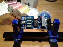
Nice boards from the DIY Audio Store. I like the polarity pads for the diodes and the electrolytic cap! I used a Panasonic JS1-24 relay as Omron bailed out. I checked around and it looks like there are many relay substitutes. I bought the big chunky screw terminals but in the end I went with old fashion Faston tabs. The electrolytic is by Epcos Inc and the film cap is from Kemet.
The Toecutter board is very good, I will buy some more soon. Next is the speaker protection board.
Cheers...
Attachments
PSU board is now back in stock: https://diyaudiostore.com/collections/printed-circuit-boards/products/universal-psu
If you go to the diyaudio shop page where you ordered the boards, there should be schematics and bom.
There are many designs for soft start circuits on this Forum.
Download a few and choose one that meets your performance criteria. Then you can scratch build what you need.
BTW,
I recommend a version powered from a small isolating auxiliary transformer. NOT direct to the mains power.
Download a few and choose one that meets your performance criteria. Then you can scratch build what you need.
BTW,
I recommend a version powered from a small isolating auxiliary transformer. NOT direct to the mains power.
BTW,
I recommend a version powered from a small isolating auxiliary transformer. NOT direct to the mains power.
Andrew,
Any particular reason for that?
Safety !
Andrew,
Please correct me if I am wrong, but the diyAudio Soft Start V3 is also directly powered by the mains, right?
http://www.diyaudio.com/forums/diya...supply-soft-start-board-v3-4.html#post3792484
I have some questions about the circuit used in the soft-start, which you can view HERE. This is pretty much exactly the same circuit that I found posted here on the web some years ago that was dated 2001, and I assumed the circuit was adapted from that. There are lots of similar versions out there. I decided to model it in a SPICE modeler to see if I could create it using appropriate components that I already have lying around.
I could not figure out what the 220 Ohm resistor is supposed to do. The circuit behaves the same when this component is deleted, with the only difference being a couple of tenths of a volt difference in the voltage that the caps are charged up to. Why is this included in the circuit?
Why is resistor R2 a metal film type rated for 3W? It seems that most of the power will pass through capacitor C2, and even if R2 (1M Ohm) was connected directly across the line voltage (in USA that's RMS 120Vac) the power dissipated in R2 would be only about 0.015 Watts. Would not a 1/4W MF resistor be OK here?
Also, why is R2 even in the circuit? Is it acting like a "bleed" resistor? But this is an AC application... The circuit still seems to work the same when I remove it from my SPICE circuit.
Finally there is the zener, D5. This has a breakdown voltage of 24V. I assume this was put there so that the relay coil voltage could not exceed the rated value of 24Vdc. I can't figure out any other possible use for it. It seems completely unnecessary, because the voltage on the coil will just ramp up to the max voltage and then stay there. If you choose the value of capacitor C2 correctly the voltage will never even get to 24V.
When choosing components for the circuit, the value of C2 must be chosen based on the relay's coil resistance and pull-in voltage. Some of these other components do not seem to really have a useful function, unless I am missing something, and it seems the circuit could be simpler.
I think the series resistors are there to keep the current down (a bit) as the timing capacitor charges. Which seems a bit odd.
I do remember somebody suggesting (Mark Johnson?) that an easy way to get more time to charge the cap, and therefore add more time delay, was to run as much current as possible through the LED, as it will drain some current as it's charging. I think he went as far as saying one should use a high(er) current LED to drain off as much as possible. I want to try that as the delay seems pretty short.
I do remember somebody suggesting (Mark Johnson?) that an easy way to get more time to charge the cap, and therefore add more time delay, was to run as much current as possible through the LED, as it will drain some current as it's charging. I think he went as far as saying one should use a high(er) current LED to drain off as much as possible. I want to try that as the delay seems pretty short.
After doing some more web searching I seem to have identified the purported uses for R1 and R2 in the soft-start circuit.
R1: according to what I found, R1 is used to limit the inrush through C2 when the power is first applied. In my SPICE modeling this component only reduced the peak current by 1% or so, and there was no inrush anyway. The current through C2 does not change over time. As far as I can tell, R1 provides no benefit to this circuit.
R2: again, according to what I could find, R2 is a "bleeder" resistor. I went back to do some checking of this in my SPICE simulation. What I realized was that when I had looked into this previously I happened to choose the zero-crossing time of the mains AC to shut off the input voltage. In that case there is no charge on the cap, but on the other hand, if you happen to disconnect power right at the peak of the mains voltage, the cap is left with around 170V across it. R2 will bleed the latent charge from the cap and the voltage will drop to zero. Keep in mind that this circuit is part of an amplifier, and there are other paths through the power supply (fed by the same mains connections) that can bleed off the charge as well. If this resistor is included in the circuit, it could be a 1/4 watt type as long as the resistor has a 250VAC or higher voltage rating. The power dissipation when the value is 1M or higher is very low and even a 1/4 Watt is plenty. 1M will bleed down the voltage in about 10 seconds.
I think the series resistors are there to keep the current down (a bit) as the timing capacitor charges. Which seems a bit odd.
I do remember somebody suggesting (Mark Johnson?) that an easy way to get more time to charge the cap, and therefore add more time delay, was to run as much current as possible through the LED, as it will drain some current as it's charging. I think he went as far as saying one should use a high(er) current LED to drain off as much as possible. I want to try that as the delay seems pretty short.
I've been playing around with this circuit (specifically the transformerless power supply, or "TPS", used in the soft start) and I think I am getting a good feel for how it can be used, and when it can't. The cap is just a reactive element that drops the mains current. In a sense, the cap reactance and load of the relay coil act much like a voltage divider in that if you change the load resistance the voltage across it will also change. When the TPS is connected to a relay that is supposed to just "fire" as soon as the voltage across the smoothing cap charges up high enough this works well. If you have a circuit that has a change in load impedance at some point, this will impact the voltage that the TPS is delivering to the load.
I happen to have a ton of LM555 timing chips. These are pretty handy and can drive a 12V relay directly. You can use them to create delays of seconds or even minutes if you want, so if you want to charge up your cap bank really slowly, or do some other action many seconds after power up these can work well. But when powered by the TPS, if you connect the output pin to the relay coil (as a drain) with the other end of the relay coil connected to the TPS you get so large of a drop in voltage when the relay is energized that the relay will open again and the LM555 goes below its min voltage! Fail.
The problem is that the current consumption of the circuit changed from almost nothing to several tens of millivolts and this causes the TSP voltage to sag. There is a modification of the 555 circuit that you can implement to prevent this: connect the output pin both to the relay, and to ground via a resistor that is equal to the relay's coil resistance. As long as the 555 output pin is high, the relay coil has 0V across it. At the same time, because of the additional resistor connected from the 555 output pin to ground, when the output pin is high the LM555 is sourcing current to ground equal to the current needed to drive the relay. On the changeover of the output pin state to LOW (e.g. ground) the output pin is now sinking current through the relay coil. But the amount of current that the circuit is consuming has remained the same because now current is passing through the relay instead of passing through the extra resistor we added between the output pin and ground.
Because the current consumption of the circuit is constant and below 100mA, it's a good candidate for the transformerless power supply.
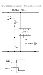
I have attached a naive circuit schematic for an LM555 configured for "delay-on-make" operation with the extra resistor added. It shows the "extra" resistor that I mentioned adding to the circuit as R2, from pin 3 (output) to ground. The relay coil would be connected between the V+ rail and pin 3. When the time set by R1 and C1 causes pin 3 to go LOW (as shown by the little diagrams at bottom) the relay coil becomes energized. Keep in mind that the LM555 has a maximum supply voltage of 16V, and a 15V zener in the TPS can make sure that this limit is obeyed.
If anyone is interested I can post the full monty circuit of TPS+555 timer+relay from my SPICE sims. They show that this can work well for longer delays as long as the relay can be activated with up to 15V and total circuit current consumption is less than 80-100mA. Or perhaps I should start a new thread about this topic in the Power Supply forum...
Attachments
I did a little more work in the simulator. I realized that I also forgot to change the phase angle to 90deg of the applied main power to test for inrush. Sure enough you DO need that 220R series resistor or the initial current for the first half cycle is pretty high. I discovered this when I added a fuse and found that even a 1A fuse was "blowing" in my sim for a circuit that only draws 80mA nominal power. Glad I figured that out! This happens because the cap is like a dead short at turn on. Even though it is only a small value around a millifarad, there is a brief current surge until enough charge accumulates.
- Home
- The diyAudio Store
- Power Supply Soft Start Board (V3)