leadbelly,
wg_ski was trying to get two different voltage power supplies out of a single CT HV winding.
He was the one that wanted to ground one end of the secondary, and then ground one end of the bridge rectifier.
Short! Smoke!
Read Post # 15.
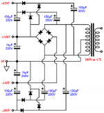
I had already proposed 2 sets of 2 diodes, a grounded center tap, and then one set of 2 diodes driving a choke input filter for lower voltage B+, and 2 other diodes driving a cap input filter for higher voltage B+.
B+ voltage output ratio: 1.414/0.9 = 1.57:1
It does not get simpler that that, or does it? Well maybe . . .
Or, you can use a voltage doubler, and pull the lower B+ voltage from the bottom capacitor (I do not like that solution, even though it works).
"You should make things as simple as possible, but no simpler" - Albert Einstein
wg_ski was trying to get two different voltage power supplies out of a single CT HV winding.
He was the one that wanted to ground one end of the secondary, and then ground one end of the bridge rectifier.
Short! Smoke!
Read Post # 15.
I had already proposed 2 sets of 2 diodes, a grounded center tap, and then one set of 2 diodes driving a choke input filter for lower voltage B+, and 2 other diodes driving a cap input filter for higher voltage B+.
B+ voltage output ratio: 1.414/0.9 = 1.57:1
It does not get simpler that that, or does it? Well maybe . . .
Or, you can use a voltage doubler, and pull the lower B+ voltage from the bottom capacitor (I do not like that solution, even though it works).
"You should make things as simple as possible, but no simpler" - Albert Einstein
wg_ski was trying to get two different voltage power supplies out of a single CT HV winding.
He was the one that wanted to ground one end of the secondary, and then ground one end of the bridge rectifier.
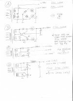
Here are a couple of ways to get various voltages from a cheap 120-0-120 isolation transformer.
What wg_ski meant was something as shown as in sketch "A".
Attachments
Last edited:
I like 'A', but only if you have equal load currents. Great!
'B' is quite lovely, 2/3 wave.
'C', I already mentioned that.
'D' does not have a dual winding with a wired center tap.
It requires two completely different secondaries.
Might as well make one winding the higher voltage winding, and the other winding the lower voltage winding.
Kind of like I said, except I used a winding with a center tap, and =/- lower voltage taps, and +/- higher voltage taps.
Refer to the very powerful One Electron Power Transformer. There are other transformers like that.
As Frank Reps once said, "Good things are not cheap! Cheap things are not good!".
I did not say that, he did.
This is an obscure riddle for you; who remembers that magazine article?
The amplifier in the article was a real good one.
Please report back if a mistake in wiring, or voltage ratings of caps and diodes, or direction of capacitors is made on any of those power supplies, and the smoke comes out.
Last edited:
I went ahead and built the 4x8 doubler. I haven't hooked it up to anything yet though. I got to thinking though.. Couldn't I just use the 6DJ8s that I already have with the doubler? It would seem that a ~40k resistor would get it to roughly 8-9 mA at 90ish volts on the anode. It would dissipate a little heat, but nothing excessive if I'm not mistaken. I don't know if such a high plate resistor would negatively affect the tone though.
If I had this to do over again, I'd definitely do several things differently. This has evolved from one thing to another for over a year now. The 170v Edcor transformer I'm using now was only about $45. I figure I might as well use it. I've got a couple of other tubes I want to play with after I get finished with this though, so I definitely appreciate the help.
If I had this to do over again, I'd definitely do several things differently. This has evolved from one thing to another for over a year now. The 170v Edcor transformer I'm using now was only about $45. I figure I might as well use it. I've got a couple of other tubes I want to play with after I get finished with this though, so I definitely appreciate the help.
FYI, schematic A in post #23 is a vintage classic used by Philips, especially for their PA audio amps using the TV tube 6CM8/EL36. It allows the 50% output to directly feed the pentode screens, and the 100% output to feed output stage B+, as well as pre-stages. The TV pentodes required a restricted low B+ for robust operation. AWA amps went up to sextuples of the 6CM8, for 100W plus PA requirements. Afaik, there is no concern with independent loading of the two B+ rails when both are capacitive filtered via ss diodes.
Last edited:
Never said to ground the bottom?
Quote from Post # 15:
"You can do full wave like that - you’re not limited to half wave. You’re thinking of a doubler where you connect to the middle. You need to start with a 120-0-120 trafo which would still be a commodity item. Just connect it as you would a big solid state amp supply, but ground the bottom not the center. The 340 volt is a full wave bridge, and the 170 a 2-diode full wave center tapped with the diodes in the ground side. You may be stuck with cap input filters - I’ve never tried it with chokes. I do this for big class H amps all the time - one transformer for high and low + rails, one for the -‘s."
Excerpt from the above quote: "but ground the bottom not the center."
As soon as I see a complete schematic of it, and analyze it, and see that it will fulfil the original posters requirement (except for the exact voltages, just the limited number of secondaries that the OP had) . . .
Then I will agree.
Till then . . .
Last edited:
JasonWatkins,
Were you ever able to build a working power supply from the suggestions that were given in this thread?
We are at Post # 31.
Please let us know the results.
Thanks!
Were you ever able to build a working power supply from the suggestions that were given in this thread?
We are at Post # 31.
Please let us know the results.
Thanks!
Last edited:
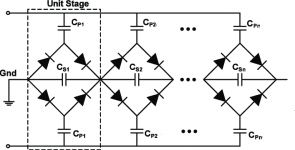
FWIW, the most sophisticated voltage multiplier I am aware of is the provided full wave series/parallel setup. Each stage is a 4 diode bridge. Polarized electrolytic caps. are OK in the series positions, but (IMO) caution requires AC rated film caps. in the parallel positions. The required voltage rating of the parallel position caps. increases, as "movement" away from the point of AC application occurs.
Bipolar PSUs, with possibly differing rail voltages, are possible using this technique. On the AC feed "side", all that's needed is a simple winding of sufficient V/A rating.
I haven't seen this one before. Eli, what makes this scheme "most sophisticated"? What are some of the advantages over other multipliers?
Attachments
- Home
- Amplifiers
- Tubes / Valves
- Power supply question - Voltage Doublers