The problem is that the whole thing can't work with "High" DC voltage because of NE555 will burn out.
The 555 only needs enough voltage to drive the MOSFET. You could easily run the circuit off a 100V supply (or whatever) and simply tap off a low-voltage supply for the 555, with a 12V zener or something. A CMOS 555 consumes very little power.
Over the years, on this site and others, there have been a number of references to switching power supplies. I’ve mentioned that I use a converted computer power supply to power the heaters of my ST-35 amplifiers. I’ve also been asked how to do this, but it’s a very difficult question to answer individually. Although the basic principle is all the same, circuits vary widely even between supplies from the same manufacturer.
I believe that I’ve devised a simple low cost heater supply solution that should make modifying computer supplies, well, hopefully a thing of the past.
For anyone interested, here’s the link:
Unique Tube Heater Supply
I believe that I’ve devised a simple low cost heater supply solution that should make modifying computer supplies, well, hopefully a thing of the past.
For anyone interested, here’s the link:
Unique Tube Heater Supply
IMO the benefits of using a smps in a tube amp are well worth it. The real reason I think people avoid using SMPS is that there is nothing commercially available. That and designing an SMPS to perform at that voltage is not a job for amateurs.
I would love is someone created an adjustable SMPS power supply to use for building tube amps. I bought the one that siliconRay was selling but I have not found a project for it due to it's HV output being only 280V. An SMPS that could get to the 450-500V range would be ideal. Anyone out there interested in designing one for us?
If you want some examples of tube gear that is using an SMPS check out Pete Millets tube mic preamp . It is easy to see in the graphs just how much a tube preamp can benefit from moving the switching frequency outside the audible range.
Here is another amp that I think is pretty impressive.It uses a stack of Cisco SMPS power supply to power a 826 and GM70.
I hope they checked the common mode voltage specs for those series connected Cisco SMPS. Very unusual for 48V SMPS to be rated for 1000V isolation!!!
Attachments
Last edited:
I have designed a hybrid one. The downside is that the volume and efficiency are not quite up to SOTA switchers standards, but it offers many advantages: no need for custom magnetics, better efficiency than traditional supplies, better utilization of the transformer (PF~=1) and excellent flexibility: the transformer does not need to have a well-defined voltage, something like 15 ~ 60V is suitable.An SMPS that could get to the 450-500V range would be ideal. Anyone out there interested in designing one for us?
It is versatile enough to be used in a fully variable lab supply. For a semi-variable application it would be even easier.
http://www.diyaudio.com/forums/power-supplies/230360-high-voltage-variable-supply-shoestring.html
hammond trafos are not expensive, cheaper than isolation 230/230 trafo
True. Other cheaper options exist in Europe too. you can do a voltage doubler circuit to get 400V - be careful to ensure current demands are met hough.
Good question. Less tinkering with the powersupply..no tube rectum fryers.....is what diy´er actually like. so that may be held against smps....etc. But if I ever come across a truckload of those power supplies for a good price. I´ll know what to use them for.Why aren't switched mode power supplies common in tube amplifiers?
In the case of manufacturers...it perhaps is a case of marketing?
https://greenvalve.wordpress.com/
https://www.youtube.com/watch?v=HBXbseGQFfg
Last edited:
Cost price vs units sold? You can compare a PC PSU for complexity, better models sell for $100. Triple that for low volume HV supplies. Wanna buy?
IMO the benefits of using a smps in a tube amp are well worth it. The real reason I think people avoid using SMPS is that there is nothing commercially available.
I would be concerned about HF noise. Yes, it's well outside the audio spectrum, but it can get modulated / demodulated in amplifiers, and it has an influence on the sound.
Here is another amp that I think is pretty impressive.It uses a stack of Cisco SMPS power supply to power a 826 and GM70.
Adding up the noise from 18 stacked SMPS is impressive, indeed... 🙄
I have a Peavey bass amp - VB3 - which has a SMPS powering 8 Ruby BHT EL34s for 300 watts. The advantage is it weighs 37 lbs, vs: an Ampeg SVT which weighs 85 lbs. B+ on this HAS to be at least 500V, don't ya think?
Here was another thread on power supplies:
http://www.diyaudio.com/forums/tubes-valves/250257-bench-power-supply-what-get.html#post3798207
Cheapest PS I could find on Ebay at the moment:
EMI 600V 1A Programmable Variable Output DC Power Supply TCR600S1 1 D 0813B | eBay
Oh, wait, here is the cheapest, $99:
(Still there from a year and a half ago!! I can't believe someone didn't buy it then after it got mentioned in that thread. You can lead a horse to the water, but you can't make them drink it. And what a dumb vendor listing, with no 600V in the title, searches can't find it.)
Em Electronic Measurements SCR Power Supply | eBay
When the last cheap one is gone:
(I used to get these super 0 to 600V supplies for $50 to $200 during the dot com bust. Now look!!! Glad I got a pile of them back then.)
Xantrex XHR600 1 7 Programmable DC Power Supply 0 600V and 0 1 7A | eBay
Last edited:
LT3751
Perhaps this has already been covered...?
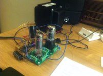
I am experimenting with the LT3751 flyback smps converter to generate the B+ for my "tube training wheels" project. The idea is to have 2x computer speaker mono-blocks but with a remote smps PSU for B+ and filament supply.
I have used a Linear Technologies demo circuit, converted from a capacitor charger to a regulated PSU providing 260Vdc at about 120mA. I have hooked this up to a SE amp using a 6SN7GT and EL84 output tube for some listening tests. So this PSU can supply both amplifiers.
The 3751 controller can with a suitable flyback transformer and mosfet supply 100W, up to 500V and 200mA according to the application notes. My current configuration does about 45W.
One challenge is that the 3751 is an almost impossibly small chip for a DIYer to solder, and pin 1 is at the back of the chip and needs to be soldered to sufficient copper to give a good heat sink.
Nevertheless, at the end of the day a small & lightweight B+ supply, with a 80-85% efficiency. In this case I have used a Texas TPS5450 to supply the 6.3V (supplies up to 5A)
The other advantage is the whole circuit can be supplied by a computer PSU brick, or as I have in my photo, an unregulated 30V supply.
Perhaps this has already been covered...?
I am experimenting with the LT3751 flyback smps converter to generate the B+ for my "tube training wheels" project. The idea is to have 2x computer speaker mono-blocks but with a remote smps PSU for B+ and filament supply.
I have used a Linear Technologies demo circuit, converted from a capacitor charger to a regulated PSU providing 260Vdc at about 120mA. I have hooked this up to a SE amp using a 6SN7GT and EL84 output tube for some listening tests. So this PSU can supply both amplifiers.
The 3751 controller can with a suitable flyback transformer and mosfet supply 100W, up to 500V and 200mA according to the application notes. My current configuration does about 45W.
One challenge is that the 3751 is an almost impossibly small chip for a DIYer to solder, and pin 1 is at the back of the chip and needs to be soldered to sufficient copper to give a good heat sink.
Nevertheless, at the end of the day a small & lightweight B+ supply, with a 80-85% efficiency. In this case I have used a Texas TPS5450 to supply the 6.3V (supplies up to 5A)
The other advantage is the whole circuit can be supplied by a computer PSU brick, or as I have in my photo, an unregulated 30V supply.
Attachments
For what it's worth..
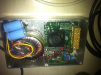
I'm in the process of building an LM2588-based flyback boost supply for a small-ish "garage" amp so I can listen to my LP's in the garage while I'm working at the workbench. I don't have any HT transformers laying about, and rather than do the "poor man's isolation" of running a 240-12-12-240 pair of transformers (which is large, messy, expensive, and wasteful) I'm using a spare 19v 9A laptop switcher.
With some effort I should have a nice little modular PCB that will work well with various laptop inputs.
I'm sure there are more effective ways to do it, but this is cheap and easy considering I get chip samples every week in the mail and I have a few 240-12 transformers laying around.
The HF noise is much easier to filter out, as it uses smaller value components, and if there is a few mVpp of PSU ripple on the voltage-amp supply at 100kHz it's not going to matter to my ears at all!
I can post the schematic if people are interested.
Cheers
Will
I just saw this on another tread. It shouldn't be too hard to modify this design to work on 120V AC. I wonder if the designer would be interested in making a universal PS for tube amps for the community.
OK, now that we are back to the original topic... I'll dive in.
I've designed quite a few offline switching supplies over the last 20 years or so, though it's not my specialty and I don't consider myself expert. Most have been normal supplies with low voltage output(s). Even then, it's not an easy task - getting the feedback loop right, and meeting all the safety rules (creepage/clearance/fire/etc.) is not trivial.
I've always wanted to design a general-purpose switcher that could provide 300-400V plus 6.3V at high enough power to run a decent tube power amp. I have designed and built one which worked, but had some issues.
One of the problems using a SMPS for tube heaters is that the cold resistance is so low. Anybody who has tried using normal switchers or wall warts has probably found that to light up 1A worth of heaters you probably need a 5A supply, otherwise the supply won't start up into the cold heaters. Sometimes they will go into restart cycles, and eventually kick in.
The supply I designed had that issue too. I thought I had enough margin in it to start up, but between charging B+ caps (there is a lot of energy stored there) and warming up the heaters, it had startup issues. The best way around that issue is probably to use a CC/CV output circuit on the secondary side so instead of cycling the supply just runs in CC mode until the heaters get up to temperature. So, that design sits on the shelf, maybe someday I'll get back to it.
There is a lot that can go wrong in an offline SMPS. I am confident that I can design a safe supply (I've done many that had to pass UL safety certification)... my worry is that if such a supply isn't built correctly, or if the builder decides to make a few "improvements" or parts substitutions, it could kill him.
Of course, you can say that about any tube amp. It just feels like there is more to go wrong.
Which brings us to the main reason that we don't see more SMPS' designed for tube amps: the transformer. You cannot find many off-the-shelf switching supply transformers (other than some common applications like USB chargers). For a useful tube HV SMPS, you would have to design a transformer, and either wind it yourself, or have it made. Designing them is not trivial - there are many more complexities in an SMPS transformer than a linear line frequency transformer. Plus there is a lot of interaction / tradeoffs made between the transformer design and the controlling circuit. I can tell you it is not practical to have a few SMPS transformers wound - the cost is ridiculous. Winding them yourself is possible - I did it for the supply I designed - but even then, finding the right core, with the right gap ground in, and the right insulating materials, is difficult. And again, screw it up, and you might electrocute yourself.
I'll continue the quest. Maybe if I settle on a design that could be popular enough, it would make sense to get some transformers manufactured.
I have another supply design that is a primary-side-control flyback that generates either 150V/300mA or 300V/150mA (give or take 25V), with no filament supply. I haven't built it yet, but I'm about to send out for PCBs to be made. It would be suitable for DIY builders, and actually uses an off-the-shelf transformer, but putting an offline SMPS in the hands of DIYers still scares me. Less to go wrong with this one, as safety isolation is all in the transformer, which can be bought off-the-shelf. I might offer PCBs for this. Gotta make sure my liability insurance is up to date.
As somebody else mentioned, it's also not too hard to make a flyback or even boost converter to generate moderate power B+ from 12V or 48V DC. The mic preamp I designed has a flyback that uses an off-the-shelf transformer that was designed to generate 12V from line voltage - I'm using it backwards. It works. You can see that schematic on my website.
I also made some commercial headphone amps that had a single-ended boost converter to take +/-15V and generate 300V at ~20mA. That one works really well. Maybe I should publish it...
The nice thing about the DC/DC supplies is that you don't have to worry about line (mains) isolation. That gets taken care of somewhere else. So even though there is still high voltage output, ground is ground.
Sorry for the long post
Pete
If one is going to start with 48VDC or so from a commercial supply, then easiest approach would be to make a Berning type switch mode OT. A very simple square wave inverter to HV, with multiple medium V secondaries, each with a bridge rectifier and series'd together. One converter for each P-P tube. You don't have to use the totem pole switches Berning did either, just connect the two LV sides like a Circlotron to the speaker.
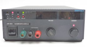
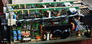
Here is a Xantrex custom designed power supply, for NASA, I found on Ebay. Dual 300 Watt, 50V-75V or 75V-155V range select switch on each. $20 each.
I modded the fans to quiet ones. Looks like a lot of parts to make one DIY. I got a pile of them a few years back. Probably can find other odd HV supplies on Ebay from time to time.
Attachments
Last edited:
I once designed this circuit for use as a 2A3 heater supply. LT1074 is not too exotic and comes in a nice TO220 package, and has a nice current limit feature.One of the problems using a SMPS for tube heaters is that the cold resistance is so low. [...] The best way around that issue is probably to use a CC/CV output circuit on the secondary side so instead of cycling the supply just runs in CC mode until the heaters get up to temperature
I did not build this circuit yet, but see no reason why it shouldn't work. Sim results are nice, with 1~2 mV @100kHz ripple using the extra LC filter network on the output. (Will be even less if using super low ESR caps)
The downside is the LT1074 needs ~8V minimum input voltage, but you can easily get this using voltage doubler rectification from any spare heater xfmr windings.
Attachments
If anyone is interested I have a 13.8v smps design for tube amps on my website. I’m also near completion of a universal 13.8v smps. For anyone looking to design one around off the shelf components I suggest reading this. The information is spot on and I have built several working versions of it. To power a bunch of heaters use a lm317 to drive the base of a tip31. Tie the collector to your power source. Adjust the lm317 to 7v and you will have 6.3v@3a on the emitter. You can choose a larger tip or parallel tips to achieve any current your power source can supply. The lm317 does not need a heatsink but the tips will.
- Status
- Not open for further replies.
- Home
- Amplifiers
- Tubes / Valves
- Power supply options for tube amplifiers.