Hey guys, the project I am currently working on only slightly has to do with audio. The goal is to syncronize lights to music. I am currently having a PIC control everything. I didn't have any triac's handy and was having a hard time finding good schematics for them for what I am trying to do, so instead decided to use MOSFETs to switch the mains voltage. The problem is that mains voltage is AC and MOSFETs can't switch AC. So I simply put a bridge rectifier on the mains source giving me a 120V 120hz pulsed DC. Since I am merely switching a light bulb, this is no big deal.
Enough background. I found that the MOSFET only worked when I tied the - side of the bridge rectifier to my +5v power supply ground. That supply is what is being used to switch the MOSFET. This causes a different problem though. Now, my ground is 60V higher than the ground in my wall and in all of my other electronics. I measured with a voltmeter my ground and the ground on a few of my amps as well as the ground in an outlet to confirm this. So now I can't connect my circuit to any others because the grounds are way off and would cause a short... I know there must be something simple I am missing, but I can't figure out what it is.
Thanks!
Zach Dwiel
You need to use opto isolators to drive your FETS and a seperate isolated +5VDC supply for the HOT side of the opto isolator. BE VERY CAREFULL. This could be a shocking experince.
Thanks for the info!
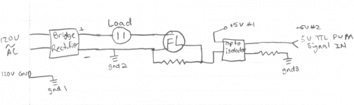
Here is an attached picture of the schematic I am thinking of. It is slightly different than what I have built and was using which prduced the wrong and unsafe grounds. Does what I haev drawn look correct? I am not sure however which of my grounds can all safely be connected. My biggest worry is 'gnd1'... I doubt that I can connect it to 'gnd2' because of the said 60V difference when they are not connected. I have found that the only way to get the FET to switch is to connect gnd2 and the gnd associated with +5v#1. I also understand that +5v#2 and its associated gnd3 must be isolated from all of the others in the circuit, but I'm still not 100% sure how isolated they need to be. Do I need 2 transformer/bridge/cap/vreg sets for each? Or can some of those be shared? Maybe only have a single transformer and 2 bridge/cap/vreg sets comming off of that or something like that to cut down on size and cost.
Thanks abunch for the help!
Attachments
Dwiel said:Thanks for the info!
Here is an attached picture of the schematic I am thinking of. It is slightly different than what I have built and was using which prduced the wrong and unsafe grounds. Does what I haev drawn look correct? I am not sure however which of my grounds can all safely be connected. My biggest worry is 'gnd1'... I doubt that I can connect it to 'gnd2' because of the said 60V difference when they are not connected. I have found that the only way to get the FET to switch is to connect gnd2 and the gnd associated with +5v#1. I also understand that +5v#2 and its associated gnd3 must be isolated from all of the others in the circuit, but I'm still not 100% sure how isolated they need to be. Do I need 2 transformer/bridge/cap/vreg sets for each? Or can some of those be shared? Maybe only have a single transformer and 2 bridge/cap/vreg sets comming off of that or something like that to cut down on size and cost.
Thanks abunch for the help!
OK, let's see here.
Grd 1 is AC ground and should be connected to the chassis.
Grd 3 is circuit Grd for +5v#2 and the PWM circuits.
Grd 2 should not connected to ground. It is the - connection for +5v#1 and must be isolated from all grounds.
Do I need 2 transformer/bridge/cap/vreg sets for each? Or can some of those be shared?
You need a seperate isolated power supply for +5v #1. It does not need to be regulated. It can be just a transformer / bridge / cap. It can be very low current, less than 100 ma is OK.
I think I would put the load on the other side of the bridge rectifier in the neutral side of the AC line as shown in you drawing.
I say again BE CAREFULL.
 Use an isolation transformer! This is a potentially deadly circuit.
Ditch the MOSFETs. Go buy some TRIACs. Its really not that hard.
Use something like the MOC3021 (?) isolated triac driver.
Stay alive.
Are your lights going on/off or are you trying for dimming?
This is a dangerous circuit. Make ONE mistake and pouf, you'r dead meat.
If you don't have a good life insurance yet, this is probably an excellent reason to get one....
Jan Didden
If you don't have a good life insurance yet, this is probably an excellent reason to get one....
Jan Didden
Thanks for the suggestions guys! I guess I'll be switching to triacs rather than PWM controlled MOSFETs. I do have a few more questions though. I'd rather be safe than sorry in this case... I've already been shocked by this system once, am I lucky to be alive?
First, why does using a triac make the circuit safer? Is it that I don't have 120VDC? I assume thats the main concern.
Second, I definately want to be able to dim the lights, and hopefuly do so with a fair amount of control and speed. I assume I will still be able to do this with a triac. Am I correct that the triacs always switch at the same frequency as the mains? From what I've read, it looks like they simply shorten each cycle. How much extra electronics am I going to need in order to adapt my PWM signal into an in phase, correct frequency one. I guess making it the correct frequency shouldn't be a problem, but making it in phase might... Is that a necessity?
I have seen many triac controlled light dimmer schematics online. Would I be able to simply replace the pot with an optoisolator? I could then send my PWMsignal at any frequency and any phase to that in order to control the brightness. Would this work?
I guess the goal would be to have a simple, safe circuit which could take a high frequency (higher than audible) PWM signal and control the brightness of a lamp off the mains power with it.
Thanks agian for all of the help! It might be advice which saved my life. 😀
If you already have the pwm signal up and running, you can drive solid state relays with it. That is what 99% of modern dimmer packs use. They are much cleaner and easy to drive.
A lot of solid state relays I am finding don't report the on/off time which I am slightly worried about. I can adjust my PWM frequency, but I'd rather not have to. Right now, the max frequency is around 20,000hz Can most solid state relays switch that fast? Or should I make sure I find specs on them before I buy them? I would need them to be able to turn on and off around 2.5 or maybe 5 microseconds. That would allow me to use a 20khz PWM and get a maximum of 90% full power to my lights.
Although after a little more looking, it's looking like even fast solid state relays take 0.05 ms to switch, which is still 50micro seconds which is way to long for a 20khz PWM. I think, please correct me if I am wrong.
Maybe I should just stick to triacs. I assume they switch plenty fast enough?
Although after a little more looking, it's looking like even fast solid state relays take 0.05 ms to switch, which is still 50micro seconds which is way to long for a 20khz PWM. I think, please correct me if I am wrong.
Maybe I should just stick to triacs. I assume they switch plenty fast enough?
- Status
- Not open for further replies.
- Home
- General Interest
- Everything Else
- Power Supply Ground Confusion