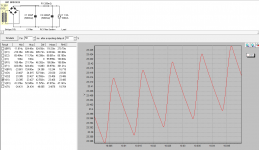
I found that looking at the ripple on the scope clearly shows the advantage to adding on an extra stage of {R+L}C
The standard rC shows quite sharp peaks at the top and bottom of the ripple voltage.
Changing that to rC{R+L}C shows a very rounded curve at the top and an even more rounded bottom to the ripple waveform.
The reduced level of ripple peak to peak shows that the 100/120Hz fundamental is reduced. The rounded curve compared to the sharp pointed curve shows that the proportion of HF harmonics is much reduced.
So you have a general reduction of the fundamental and a very much reduced harmonic content.
lLok at your scope when the PSU is under some loads.
I found that looking at the ripple on the scope clearly shows the advantage to adding on an extra stage of {R+L}C
The standard rC shows quite sharp peaks at the top and bottom of the ripple voltage.
Changing that to rC{R+L}C shows a very rounded curve at the top and an even more rounded bottom to the ripple waveform.
The reduced level of ripple peak to peak shows that the 100/120Hz fundamental is reduced. The rounded curve compared to the sharp pointed curve shows that the proportion of HF harmonics is much reduced.
So you have a general reduction of the fundamental and a very much reduced harmonic content.
lLok at your scope when the PSU is under some loads.
thanks Andrew,
i do not have a scope with me.
before switching my 0.25Ohm resistors with hand wound air core inductors i thought i would simulate and see if it makes any difference. looks like low value inductors do not do much in terms of filtering.
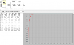
in the below graph the waveform across the first C [Green] is almost same as that is across the load [Red]
today i was playing around wit PSUD2 to simulate how would my new hand wound air core inductors would fair in a CLC filter against CRC.
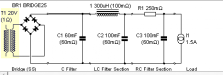
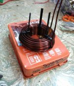
the air core inductors are made with 13 AWG wire, around 1.5 inch of diameter and 1 inch length - around 80 turns. each of these weigh 500 grams have a resistance of 0.1 ohms. on calculating the inductance turns out to be measly somewhere around 350uH [micro Henries].
simulation on PSUD2 is far from encouraging. i was under the impression that if not indcutance, atleast resistance [0.1 ohm] in the coil would act as CRC.
CLC simulation:

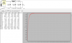
CRC [R at 0.25 ohms]:

interestingly if i run the simulation for CRC with 0.1 ohms resistance, the output graph is very close to above CRC.
this is the first time i'm using PSUD2 and not sure if i've set parameters correctly. to look at it has simple UI.
so low value inductor is bad in filtering even with inherent coil resistance?
Last edited:
It will take you a large air cored inductor to do any good. I don't think 13 gauge will give you enough reactance before the resistance is a problem, I was down to, and working with 9 gauge. It gets out of hand. Maybe you could wind both chokes together on one large core (I didn't get to test this though, it was just what I was considering around the time I found my own solution.)looks like low value inductors do not do much in terms of filtering.
It will take you a large air cored inductor to do any good. I don't think 13 gauge will give you enough reactance before the resistance is a problem, I was down to, and working with 9 gauge. It gets out of hand. Maybe you could wind both chokes together on one large core (I didn't get to test this though, it was just what I was considering around the time I found my own solution.)
Thanks Allen for sharing your experience. I expected the resistance of the choke to help in filtering just the way PSUD2 showed with CRC filter with 0.1 ohms. Looks like the way choke work is a lot different from the resistor.
This is the inductor that I have with me. Being 13 gauge wire it's difficult to work with. Now I've 4 of these and looks like these will end up in my showcase as showpieces 😛
Hello,
In a few weeks time my friend in Vietnam will get a pair of lundahl ll2733 for one of his Nelson pass designs. I think most air core chokes will do not much filtering. You will have to get yourself a pair of lundahis.
Like I wrote before the French start using chokes for ss amps in the eighties and I did the same in my hiraga. There are also some people who use chokes in their dac which also takes a hight current. All this has been mentioned before. So do as you like lol
Greetings, Eduard
Hello,
In a few weeks time my friend in Vietnam will get a pair of lundahl ll2733 for one of his Nelson pass designs. I think most air core chokes will do not much filtering. You will have to get yourself a pair of lundahis.
Like I wrote before the French start using chokes for ss amps in the eighties and I did the same in my hiraga. There are also some people who use chokes in their dac which also takes a hight current. All this has been mentioned before. So do as you like lol
Greetings, Eduard
hi Eduard, thanks again for your suggestion. probably i should've checked PSUD2 before making myself these air core inductors. for now i'll stick to CRC i guess.
There is a particular contribution to the sound that chokes in the supply of the Hiraga amp create but the use of a simple C-Multiplier has the ability to achieve a much wider variety of sound without the expense of large chokes - this is pretty 'old news' as a number of power supplies based around simple C-Multipliers have been built specifically for this amp - you may need to visit the Archives but there are a few current threads on C-Multipliers that are directly applicable
It seems that many amp designs do respond to having bypass caps right on the output devices but sometimes this produces oscillation &/or ringing - just something to keep in mind
It seems that many amp designs do respond to having bypass caps right on the output devices but sometimes this produces oscillation &/or ringing - just something to keep in mind
Hello,
The chokes I used in my hiraga in the eighties were bought at the French shop that did start selling this amp. It was designed for another amp but later they also used it in other amps. Outside of France I never did see anyone use this kind of choke in solid state power amps.
So most information on chokes in the hiraga amps you can find on the Internet is pretty useless because most people are using the wrong kind of chokes.
Greetings, Eduard
what frequencies do you want to filter?
If it's the fundamental @ 100/120Hz then you need a filter designed to attenuate that frequency.
If it's the high harmonics that need filtering, then the design is very different.
A filter that passes most of the 100Hz fundamental with only a 3dB loss will have an enormous filtering effect @ 1MHz and a substantial effect at 10kHz. Even at 1kHz you will see effective filtering.
Removing/attenuating the high harmonics is seen as the "rounding" of the waveform that I mentioned in the earlier post.
Hello,
I use choke input for my dac. But with hiraga dcr is important especially when used for choke input because there is a lot of voltage lost in that choke. With true choke input you would surely need another power transformer . And you need to take care of the so called critical inductance . But in the end your power supply will be something special.
Greetings, eduard
hi all,
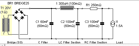
i ran few more simulations. read through few threads on how to use the PSUD2. and also one of my friends' who saw the pics mentioned that i need to adjust the load resistance at the end of the circuit. i've replaced load resistance with Q current rating- not sure if it's correct but that's the best i could come up with. this altered how the voltage responded. now finally i've a CLCRC ciruit which is better than the simple CRC.
below combination represents single rail 20,0. i'll have a similar setup for 0,-20
tried playing with combinations like CLCRC vs CRCLC and changing of C1, C2 and C3 values - finally settled for below combination. just making to do with what i already have with me. i'll report with the final output voltage tomorrow.

other option is below combination , but 'm not sure of 0.06F after rectifier- i have read in a different thread that it's better to use smaller capacitor hence i've selected above combination.
i ran few more simulations. read through few threads on how to use the PSUD2. and also one of my friends' who saw the pics mentioned that i need to adjust the load resistance at the end of the circuit. i've replaced load resistance with Q current rating- not sure if it's correct but that's the best i could come up with. this altered how the voltage responded. now finally i've a CLCRC ciruit which is better than the simple CRC.
below combination represents single rail 20,0. i'll have a similar setup for 0,-20
tried playing with combinations like CLCRC vs CRCLC and changing of C1, C2 and C3 values - finally settled for below combination. just making to do with what i already have with me. i'll report with the final output voltage tomorrow.

other option is below combination , but 'm not sure of 0.06F after rectifier- i have read in a different thread that it's better to use smaller capacitor hence i've selected above combination.

Attachments
Last edited:
The Hiraga design is quite similar to the F5 in that it's extremely sensitive to the power supply quality and a low ripple magic design doesn't necessarily guarantee a 'good sound' or even a personally satisfying sound - you need to have a listen in your own system to settle on your final supply design - for me, anything much bigger than a 10,000uF cap produces a 'downside' that's a slow and fat sound - even the BHCs exhibit this characteristic in the basic (R)-C -R-C or C-L-C -R-C supply which is why the well known 'slit foils and T-Network caps are only available up to 10,000uF
just my 2 cents ...
just my 2 cents ...
the last C is the main supply for transient current (the music).hi all,
i ran few more simulations. read through few threads on how to use the PSUD2. and also one of my friends' who saw the pics mentioned that i need to adjust the load resistance at the end of the circuit. i've replaced load resistance with Q current rating- not sure if it's correct but that's the best i could come up with. this altered how the voltage responded. now finally i've a CLCRC ciruit which is better than the simple CRC.
below combination represents single rail 20,0. i'll have a similar setup for 0,-20
tried playing with combinations like CLCRC vs CRCLC and changing of C1, C2 and C3 values - finally settled for below combination. just making to do with what i already have with me. i'll report with the final output voltage tomorrow.

other option is below combination , but 'm not sure of 0.06F after rectifier- i have read in a different thread that it's better to use smaller capacitor hence i've selected above combination.

Once this and the local decoupling of the supply rails has been fixed, you will find that the "sound" does not change much by making small alterations to the preceding stages in the PSU. It may be inaudible.
You just need to get sufficient ripple attenuation and avoid ringing if there are step changes in current demand.
All your recent plots show that the voltage rise at the PSU is substantially complete @ ~6seconds. Change your reporting delay to 10s to remove the rising part of the simulation from your results.
To see the ripple waveform shorten your reporting period from 90400ms to 100ms, or less.
Repeat all your sims to these suggested settings and make comparisons.
Last edited:
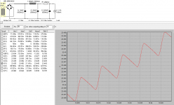
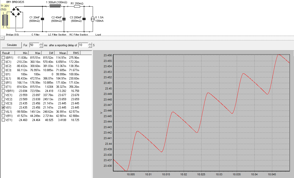
thanks so much Andrew for the PSUD settings! i was struggling to compare the waveforms. here are the results:
with CLCRC:
with CRC:
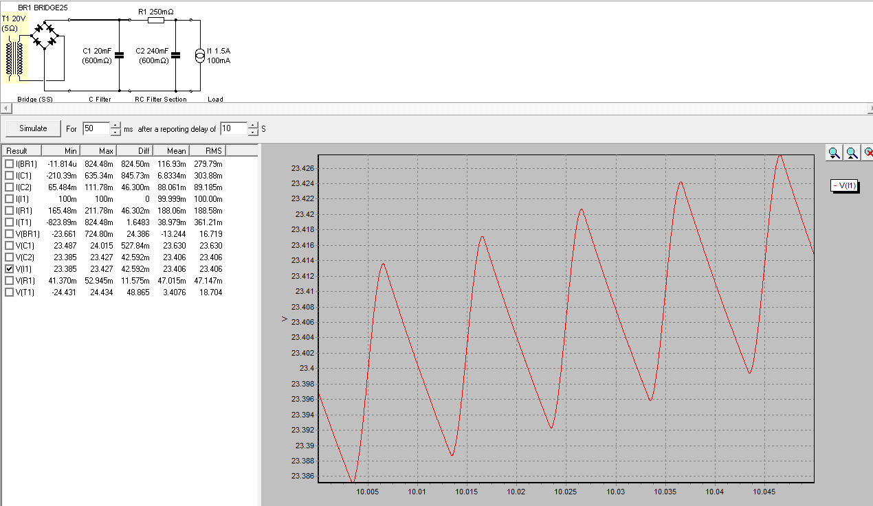
PS: i simulated the above after a 50 secs delay where it hits plateau - CLCRC waveform is smoother compared to CRC.
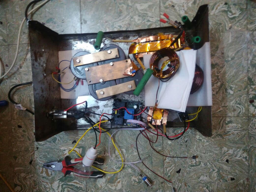
also, i built the CLCRC power supply but i'm encountering peculiar problem: when i switch on the circuit, soft start doesn't engage at first try [it has a momentary type switch]. it engages after 4 attempts and every time the in series 100W bulb blinks and on final attempt it glows and fades away slowly. once powered up, the output voltages are around 28.7 same as CRC circuit. what could be the issue?
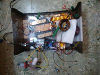
posting a pic of contraption: excuse me for ugly wiring and chassis!
[in the attached image, i just inserted extra 0.35 ohms resistor in series with inductor just to check if it makes any difference]
with CLCRC:
with CRC:
PS: i simulated the above after a 50 secs delay where it hits plateau - CLCRC waveform is smoother compared to CRC.
also, i built the CLCRC power supply but i'm encountering peculiar problem: when i switch on the circuit, soft start doesn't engage at first try [it has a momentary type switch]. it engages after 4 attempts and every time the in series 100W bulb blinks and on final attempt it glows and fades away slowly. once powered up, the output voltages are around 28.7 same as CRC circuit. what could be the issue?
posting a pic of contraption: excuse me for ugly wiring and chassis!
[in the attached image, i just inserted extra 0.35 ohms resistor in series with inductor just to check if it makes any difference]
Attachments
Last edited:
The Mains Bulb Tester is a PTC resistance in the feed.
It increases it's resistance massively when higher current flows.
That is probably stopping the start up.
You either use a fixed resistance, or an NTC resistance in a soft start to limit the start up current.
Is your soft start bypass on a timed delay, or working from a charging capacitor that has indeterminate charge rate?
A timer is far more reliable when variable input voltage is provided.
set them both to 1minute delay.
The values in the measurement table are taken over the whole of the measurement window. If the voltages are changing, the window measurement uses that change and corrupts your readings.
The rounding of the waveform is not showing. That could be because:
a.) psud does not model that
b.) the current draw is too high for the filtering
c.) ?
Try a 0.5A current draw and see if the waveform shape changes a bit, or a lot.
Last edited:
hi Andrew, i removed the series bulb and soft-start works just fine now, thanks!
with regards to CLCRC, as you said i had not set the load properly. after setting a constant current load of 0.5amps or 1.5amps, i did not see much of a difference in waveforms - same schema with 200mH simulation shows some improvement. might be induactance is very low to make a difference [your third reason?]. for now i'll ditch the idea of CLCRC and will stick to CRC.
with CRC [0.04F - 0.25Ohms - 0.24F] the ouput voltage without load is around +/-30 Volts DC for 20V AC secondary.
Hello,
You need chokes like the ll1694 or ll 2733 to really create a filter. The French people who did publish and designed the hiraga in the eighties did use 0,2 Henry iron core chokes in some of their designs. I did ask rhea in person if I could use this choke for the hiraga. They did give me a big yes.
Before the end of this month a Vietnamese friend will try the ll2733 I will bring to him in one or more of his Nelson Pass designs.
The results could be published by him on Vietnamese websites maybe also here.
Good luck with crc lol
Greetings, eduard
The choke input filter may show around .7 of the voltage at the output. You will not have a choke input filter while you have the large capacitance as the first component. You will also need something bigger, for example 10mH depending..also, i built the CLCRC power supply
...
the output voltages are around 28.7 same as CRC circuit. what could be the issue?
- Home
- Amplifiers
- Power Supplies
- Power Supply for Hiraga
