
The second one is 680nF as he wrote in the blog, but overall this guy likes too many sprinkles on his ice cream....
H
HAYK
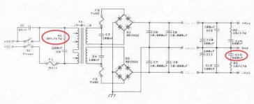
This PSU is suitable for classA amps. With classAB, only half the power of the transformer will be used or twice the voltage drop of the same transformer with common ground.
ref post 3: quote "With classAB, only half the power of the transformer will be used"
🤔
please explain......
🤔
please explain......
H
HAYK
With common central ground, when either rail gets current, both secondaries gets loaded. Here only one secondary is active at a time.
Obviously, fully regulated power supplies are not practical in typical power amplifiers running in class AB.
Pure class A is quite a different story, as it draws constant currents, so electronic regulation has a much simpler job to do. However, do not throw it out yet - we do need full regulation in a power amp.
That is a really weird comment. A reg'd supply design is just a bit more complicated to do. There is a need to know how much ripple it is intended to take out. Also the transformer voltage drop with load. The reg'd supply will stabilise that to close limits.
On class A a capacitor multiplier can do a decent job as the load current is constant. Sort of regulator that has worse load current stabilisation than a true regulator.
There doesn't appear to be any comments about how much capacitance is needed for a given max load current on a simple just smoothed supply. There are calculators around on the web.
LOL Must admit I'm not fond of the use of one bridge regulator on a split supply. I feel it leaves things a bit woolly with varying loads on each rail - they will vary when actually used to listen to music rather than sine waves.
OP, who knows what that circuits designer intended?
on the primary side, a cap of 10nf class x2 will help with switch arcing
on the secondary side, take your cue from this thread Simple, no-math transformer snubber using Quasimodo test-jig
on the primary side, a cap of 10nf class x2 will help with switch arcing
on the secondary side, take your cue from this thread Simple, no-math transformer snubber using Quasimodo test-jig
With common central ground, when either rail gets current, both secondaries gets loaded. Here only one secondary is active at a time.
so, what differance will we get when we connect these power supplies (CT+ 1 bridge Vs twin sec + 2 bridge) to an amp?
Maybe it's worth considering why something like this is needed. I feel some flannel is creeping in.
Personal experience as we did have a large local car factory and our local substation was clearly involved with it. 😉 interesting - it always happened when the night shift was at work.
So the factory has a power outrage - something takes way more current than it should do. The high voltage supply feeding the substation drops due to load. This can be a several kv drop. A circuit breaker trips so the hv line shoot back to it's usual value. Transformers have capacitance between the primary and the secondary. That causes a spike tor be transferred though all transformers connected to the circuit. In our case a filament light bulb would often blow or go dim and then get brighter than usual. In one case a dimmer on the wall exploded - cracked and blew off the cover. The TV etc was never harmed. Nothing in the house that was connected other than those mentioned.
A snubber. It has an rc time constant. You can think about it via a step input driven by DC. dv/dt will be reduced for some period of time, The cap eventually charges up. On AC the waveform will set some charge level on the cap. The cap can store some quantity of energy when a spike is introduced.
What are you trying to protect from???? What's transformer ringing got to do with it? You effectively have a short duration low pass filter. A pretty poor one.
A more modern solution
https://www.mouser.com/pdfdocs/bour...he-right-mov-surge-suppressor-white-paper.pdf
A much better general crap filter. One variant that is easy to use. 😉 Some are a bit big.
https://www.farnell.com/datasheets/3171477.pdf
Sort of thing you may find in industrial kit.
- Home
- Amplifiers
- Solid State
- Power supply filtering