Hey guys. Sorry for stupid question, but I didn't find any answer here. In what order I have to place parts designing power supply?
- Transformer -> bridge rectifier -> voltage regulator -> caps -> amp
- Transformer -> bridge rectifier -> caps -> voltage regulator -> amp
- Transformer -> bridge rectifier -> caps -> voltage regulator -> caps -> amp
1 will not work.
2 may work - depends on the regulator details
3 may work - depends on the regulator details
Read the regulator datasheet.
2 may work - depends on the regulator details
3 may work - depends on the regulator details
Read the regulator datasheet.
At this moment I'm doing it in 3rd way. But I don't think it is a best way.
It's true that a regulator can have better transient response with a smaller (or no) output capacitor.
However, some regulators require 10uF or more on the output to be stable. What kind of voltage and current do you need?
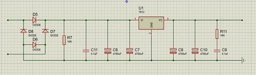
It depends on layout, parasitic inductance may cause problems, but it can work. R11 and C9 don't do anything.
7812 have different versions.
What kind of load do you have?
7812 have different versions.
What kind of load do you have?
Last edited:
what is the load? it is very naïve designing a power supply without any requirements derived from the load/system specs ( ranging from wont work correctly to a waste of parts / power resources )
what are the special requirements driving very large values of bypass caps C8 & C10 ?
why did you pick 78xx series?
learn how to specify a power supply 1st! understanding static regulation and dynamic regulation IR drops / etc.
you left off the source requirements too E.g the transformer and load do matter.
I'm trying to make kind of universal 12V PSU for experimenting with simple low power (10-25W) class D amplifiers boards from ebay or aliexpress.
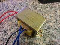
I have two 16V transformers from old pc speaker systems.
I have two 16V transformers from old pc speaker systems.
There are lot of schematics in internet with usage of output snubber resistor and capacitor.R11 and C9 don't do anything.
Attachments
The transformer sometimes needs a snubber.
The smoothing capacitors rarely (never) need a snubber.
The transformer snubber gest fitted at the transformer, not on the other side of the regulator. i.e. fitted before the bridge rectifier.
The smoothing capacitors rarely (never) need a snubber.
The transformer snubber gest fitted at the transformer, not on the other side of the regulator. i.e. fitted before the bridge rectifier.
I humbly think using these transformers is not the right decision.
With 16 Volts transformers you get roughly 22,5 Volts when rectified.
This means you will have to burn 45 % of the used power in the regulator....
You speak of class D amps up to 20 Watts rms?
These will efectivly use up to 25 Watts at 12 Volts, and 50 Watt peak.!
This is more than 2 Amps eff. and more than 4 Amps peak.!
You will burn effectivly 20 Watts in the regulator, and 40 Watts peak.
Even with a 3 Amp type in a TO3 housing on a large heatsink this is not suffcient.
A cheap switching power supply from an old laptop would be much cheaper and better.
Or a transformer with a secundary voltage of 9 Volts with a rectifier and capacitor?
Or a switching regulator with a 3 amp output (LM2575)?
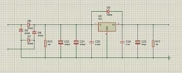
Sorry for being unclear, guys. I'm talking about large capacitor banks before and after voltage regulator. Currently I'm doing it like in attached image.
Large amounts of capacitance placed after the regulator could only provide negligible improvement in ripple rejection, and low frequency supply source impedance due to the already low output impedance of the regulator at ripple frequencies. They also needlessly stress the regulator with a high peak current draw at turn on, which will work to shorten the life of the regulator.
C11 doesn't do anything (useful).
10k plus 0.1uF is not a snubber, it is an affectation.
Big caps on the output of a regulator are often a bad idea, and usually at best unnecessary, but it all depends on the details.
Why design a low efficiency PSU to supply a high efficiency amplifier?
10k plus 0.1uF is not a snubber, it is an affectation.
Big caps on the output of a regulator are often a bad idea, and usually at best unnecessary, but it all depends on the details.
Why design a low efficiency PSU to supply a high efficiency amplifier?
common linear regulators need approx. 3-5V of of headroom before they drop-out. anything more is a waste of power and requires it to get rid of the heat. Those are nice transformers, 1st use proper rectification with all windings used otherwise yer wasting about half its VA. Consider using a DC/DC buck converter before the linear regulator*, that way you can adjust the voltage before the linear regulator an still maintain regulation and wasted power. Also consider using an adjustable linear regulator design rated for >2Amps. BTW large capacitor banks are provided by the class D amps PCB, by using regulated supplies more supply bypassing isn't necessary or better.
*google 'LM2596 DC/DC buck converter' then choose wisely
*google 'LM2596 DC/DC buck converter' then choose wisely
Last edited:
I wouldnt bother with a regulator for class d.
Just use well smoothed DC.
Most class d with feedback will tolerate a bit of noise on the power rails.
Class d without feedback is a totally different matter.
Just use well smoothed DC.
Most class d with feedback will tolerate a bit of noise on the power rails.
Class d without feedback is a totally different matter.
There are more options here than you can shake a stick at. Lets start with free. You probably have an old computer power supply laying around or have a friend that has one. It has the 12 vdc that you want.
You have two transformers 32 volts center tapped also written as 16-0-16 at 1.6A, i believe the 1.6A refers to the current across the entire winding of 32 volts because of the 3 wire secondary. You cannot wire the 16 volt winding's in parallel because you would need both wires for the two 16 volt winding's.
So you have 32 volt x 1.6A = 51 watts. You have two of these transformers so if used together you have for this discussion 100 watts. Paralleling the two transformers would give you the same voltage 16-0-16 but double the current. You would have 1.414 x 16 = 22.6 vdc - diode drop = 22 vdc plus around 10% drift up no load = 24 to 26 volts.
This means you could make a +- 25 vdc power supply at 100 watts. Just transformer, bridge rectifier, and capacitor. This would work fine for higher power amps. Some amps require a single supply and some require a +- supply. You could do both with this setup, assuming you want to do higher power amps.
You could also use just one of these transformers and use the simple switcher chip as others have said. But this depends on your electronic know how and building skills.
But as i said there are many options open to you. BTW the lower power chips usually max out at 24 vdc if not for anything else the china boards usually only have 24 vdc capacitors installed in them. So the 24 to 26 vdc from a unregulated transformer would be to high18 to 20 vdc would be about right. Which is to bad as it would make things much simpler.
he wants to experiment, besides V regulators let you adjust supply voltages to meet various chip amp requirements. its true class D puts garbage on the rails, why risk mixing it up with switchers putting IMDs back in band.
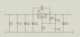
Well for op-amps, a 9V transformer works fine (you'll get around 12V after rectification and filtering).
For chip amps, the voltage requirement is not that strict and transformers have standard secondary voltages, so you're better off changing the transformer rather than dealing with regulators.
For chip amps, the voltage requirement is not that strict and transformers have standard secondary voltages, so you're better off changing the transformer rather than dealing with regulators.
Output puffer cap is good for the very high current spikes drawn by an amplifier and also for receiving reactive kickback. 1 A average is enough for quite high music power. LDO gives the ability to adjust voltage for different amps, and protected. So basicall this design is very good. But the optimum is omitting LDO and use an amp with 24V supply voltage rating. That transformer is perfectly enough. SMPS is an opportunity for mess things up.
- Status
- Not open for further replies.
- Home
- Amplifiers
- Power Supplies
- Power supply design question