I'm a bit of a NOOB and could really use some help at this point.
My friend has a Martin Logan MLT2 subwoofer that "doesn't work" so he's letting me play with it in case i can revive it. The power light does not turn on so i'm looking at the Power circuit first. A few pics are included to help (I hope).
While looking at the primary side, i came up with several questions:
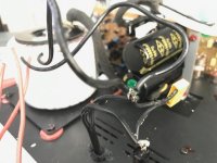
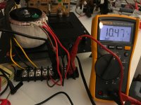
1. I can't seem to measure the capacitance across the yellow Tenta Mex X1 0.1uf suppression cap. The measurement on my fluke says OL (overload). The AC Voltage across it is a clean 121Volts. Does that mean it is faulty or ok?
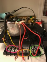
2. I don't fully understand the primary definitions - 0v-115v and 0v-115v but there are 5 wires blk red blk red brn. Is brown the ground wire? It's connected to the shield of the fuse so maybe it is.
3. The power caps measure very close to their rated 6800uf rating so they seem ok. When i turn on the unit, I measure 56Volts across each cap. Can i assume the power is good to this point and begin looking further into the circuit? Like beginning to probe into other elements in the circuit board with the power caps on it.
As always, your comments are well appreciated.
KF
My friend has a Martin Logan MLT2 subwoofer that "doesn't work" so he's letting me play with it in case i can revive it. The power light does not turn on so i'm looking at the Power circuit first. A few pics are included to help (I hope).
While looking at the primary side, i came up with several questions:
1. I can't seem to measure the capacitance across the yellow Tenta Mex X1 0.1uf suppression cap. The measurement on my fluke says OL (overload). The AC Voltage across it is a clean 121Volts. Does that mean it is faulty or ok?
2. I don't fully understand the primary definitions - 0v-115v and 0v-115v but there are 5 wires blk red blk red brn. Is brown the ground wire? It's connected to the shield of the fuse so maybe it is.
3. The power caps measure very close to their rated 6800uf rating so they seem ok. When i turn on the unit, I measure 56Volts across each cap. Can i assume the power is good to this point and begin looking further into the circuit? Like beginning to probe into other elements in the circuit board with the power caps on it.
As always, your comments are well appreciated.
KF
Attachments
The power caps measure very close to their rated 6800uf rating so they seem ok.
When i turn on the unit, I measure 56Volts across each cap.
Sounds ok so far, but please be extremely careful, this is very dangerous!
Sounds ok so far, but please be extremely careful, this is very dangerous!
looks like one those cheap OEM chinese modules...recommend into the bin ASAP
The big capacitor show a voltage rating of 80V
That is well above the expected maximum voltage from a 36Vac transformer.
The maximum output voltage is:
Vsecmax = Vin / Vrated * Vsec * 1+regulation for a 115Vac rated primary and a 36Vac rated secondary with a regulation of 7% you can expect Vsecmax to be about 127/115*36*(1+0.07) = 42.54Vac
the maximum peak voltage into your smoothing capacitors would be sqrt(2)*Vsecmax -1Vdrop = ~59.2Vdc
80V rating is 33% higher than any maximum you should reasonably expect, except for a mains failure that breaks your 127Vac limit.
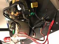
I am confused by that brown wire as well.
It looks like mains is coming in via the black 2core with one lead going to the back of the fuse holder. It's not insulated - extreme danger !
The brown wire comes from the side of the fuse holder. That is the correct location for the fuse outlet. Again uninsulated.
I don't like the X cap dangling from the mains wires. That to me is an accident waiting to happen.
The two primary windings should be paralleled for 110/120Vac operation.
Blk to blk and red to red. But that is not what I see. The two red are connected but are left floating. They should be connected to either Neutral or Live.
And the two blk should be connected to the Live or Neutral. I'm confused.
Has someone rewired this equipment?
Thanks for your comments everyone.
AndrewT, I took apart some of the foam and the wire bundling in order to do minimum probing so some things are more dangerous than when I opened the box.
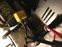
I just finished removing the shrink wrap tubing which covered the blk xformer mains and Xcap and took another pic (no_shrink_wrap.jpg). Seems like both black xformer primary wires are soldered together along with the mains black and one side of the Xcap as one node. That's 4 wires just soldered together.
The other side of the XCAP is soldered to the fuse along with the Neutral from the wall. Seems that the Hot and Neutral from the wall are separated only by the XCAP. I can see why you think someone may have rewired this.
I think I'll be salvaging this beast for parts. Many thanks for your comments and for everyone expressing safety concerns.
KF
AndrewT, I took apart some of the foam and the wire bundling in order to do minimum probing so some things are more dangerous than when I opened the box.
I just finished removing the shrink wrap tubing which covered the blk xformer mains and Xcap and took another pic (no_shrink_wrap.jpg). Seems like both black xformer primary wires are soldered together along with the mains black and one side of the Xcap as one node. That's 4 wires just soldered together.
The other side of the XCAP is soldered to the fuse along with the Neutral from the wall. Seems that the Hot and Neutral from the wall are separated only by the XCAP. I can see why you think someone may have rewired this.
I think I'll be salvaging this beast for parts. Many thanks for your comments and for everyone expressing safety concerns.
KF
Attachments
disconnect those two groups of soldered wires.
That should leave the mains input pair completely free. Insulate those two ends.
It should leave the primary side of the transformer completely free.
Insert each primary wire into a separate terminal of a screw down insulated terminal strip. You need a 5way strip.
Use your continuity tester to find which tappings are connected together. They make a secondary winding. Find out if each winding has just two ends or if you have two ends and an intermediate tap.
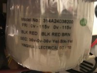
I expect to see confirmation of the transformer labelling.
PRI : 0v-115v 0v-115v which indicates two separate primary windings and only two ends on each, with no intermediate tappings.
You should find that the brn is apparently not connected to any other tapping, not to the primary and not to the secondary.
Come back with results.
That should leave the mains input pair completely free. Insulate those two ends.
It should leave the primary side of the transformer completely free.
Insert each primary wire into a separate terminal of a screw down insulated terminal strip. You need a 5way strip.
Use your continuity tester to find which tappings are connected together. They make a secondary winding. Find out if each winding has just two ends or if you have two ends and an intermediate tap.
I expect to see confirmation of the transformer labelling.
PRI : 0v-115v 0v-115v which indicates two separate primary windings and only two ends on each, with no intermediate tappings.
You should find that the brn is apparently not connected to any other tapping, not to the primary and not to the secondary.
Come back with results.
Last edited:
Hi AndrewT
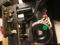
The continuity test shows that the first 3 wires starting from the left (green) are connected together and the last 2 wires on the right (blue) are connected together. The green and blue groups are isolated from each other (see pri_continuity.jpg).
thanks,
KF
The continuity test shows that the first 3 wires starting from the left (green) are connected together and the last 2 wires on the right (blue) are connected together. The green and blue groups are isolated from each other (see pri_continuity.jpg).
thanks,
KF
Attachments

OK.
The label says Blk Red. that makes your right hand pair and is a mains primary.
The label also says Blk Red Brn . It appears from your measurement that this is also a mains but with an intermediate tap.
The subtle part of that labelling is the slightly bigger gap in the printing between red and blk. That's the clue I missed.
With the Secondaries disconnected and all insulated you need to apply mains voltage to the blk red primary. BE CAREFUL. use an insulated terminal strip so that you don't accidentally touch a mains wire.
Insert the other three into an insulated 3way terminal strip.
Measure the input voltage.
Measure the other three, they are at mains voltage.
blk to red
blk to brn
red to brn
Those four voltages will tell us how they have assembled the dual primary.
Post your results, then we can move on to confirm the Secondaries.
Thanks AndrewT - not forgetting about this but I have to put this on hold for 10 days... I will get back to it after that.
It may be obvious, but have you checked the fuse??? There may be some after the transformer secondaries as well as the mains fuse holder in the panel.
Last edited:
Gopher - fuse is functioning, thx for the comment.
Andrew, pic 'Xformer ISO voltages.jpeg' shows
mains - green
primary - orange
secondary - red
Here's the measurements:
Mains: 121Volts
blk to red: 121Volts
blk to brn: 121Volts
red to brn: 0Volts
Secondary:
yellow to blk: 41Volts
yellow to yellow: 82Volts
thanks for your help.
KF
Andrew, pic 'Xformer ISO voltages.jpeg' shows
mains - green
primary - orange
secondary - red
Here's the measurements:
Mains: 121Volts
blk to red: 121Volts
blk to brn: 121Volts
red to brn: 0Volts
Secondary:
yellow to blk: 41Volts
yellow to yellow: 82Volts
thanks for your help.
KF
Attachments
I suspect, may be wrong unless tests confirm this, that you have these primaries:
* 2 wire group: Black Red 115V primary #1
* 3 wire group: Black Red 115V primary #2
Brown : thermal fused end , connected to Red #2 through an invisible thermal fuse embedded in the winding.
Not pulling this out of the blue, I have seen this somewhere else, it allows the Manufacturer to comply with the thermal fuse obbligation, but if tripped allows a "creative" Tech to "repair" amp without ordering a bulky heavy expensive transformer from Factory where very high freight (and maybe Customs) might make it as expensive as a full new amplifier.
Notice connection is to Brown wire while both Red are joined and "taped away" .
So how should knobfiddler wire this transformer?
* Brown to Live through conventional Fuse and Power Switch
* Black 1 + Black 2 to Neutral; maybe through second half of switch if it is DPST
* leave Red 1 + Red 2 taped away.
Not too late advice : build and use a lightbulb current limiter.
Don´t plug amp to mains unless specially told so, for now plug in the limiter socket instead.
The easy bit first.
The secondary is a centre tapped Y-Blk-Y, 42V-0-42Vac open circuit, when fed from 121Vac. This could make it a 120:39-0-39Vac transformer. Or maybe 115:37-0-37Vac
Now to the more complicated part.
Primary1 (Red+Blk ) is isolated from Primary2 (Red+Blk+Brn)
Label these BEFORE you dismantle.
Then check again to see if Pri1 is isolated from Pri2. Is Brn separate from BOTH Red, or connected to one Red ?
Use the Mains Bulb Tester every time you power ON.
Come back and confirm.
Last edited:
An easier test:
a) why disconnect red from red if it was factory wiring and to boot the amplifier was *already* showing the proper supply voltages?
As in:
b) the amp was *already* working by feeding one side of Mains to Brown, other side to joined Black and both Red joined and taped.
3) what you need to do now is to clean that wiring, junk for now that dangerous dangling yellow cap, you might late replace it but in a better way, connect as I suggested on answer #13 and retest you still have those +/-56V on the caps.
Once confirmed you can go on with the rest of the amplifier.
Of course, since you have been working with the mains wiring and transformer taps, for the first time plug into the lamp bulb limiter, not straight into the wall.
In that case you will measure somewhat less than +/-56V, might go as down as +/-45V , which is normal because the lamp bulb "eats" some voltage.
a) why disconnect red from red if it was factory wiring and to boot the amplifier was *already* showing the proper supply voltages?
As in:
Go back to proven working conditions.When i turn on the unit, I measure 56Volts across each cap.
b) the amp was *already* working by feeding one side of Mains to Brown, other side to joined Black and both Red joined and taped.
3) what you need to do now is to clean that wiring, junk for now that dangerous dangling yellow cap, you might late replace it but in a better way, connect as I suggested on answer #13 and retest you still have those +/-56V on the caps.
Once confirmed you can go on with the rest of the amplifier.
Of course, since you have been working with the mains wiring and transformer taps, for the first time plug into the lamp bulb limiter, not straight into the wall.
In that case you will measure somewhat less than +/-56V, might go as down as +/-45V , which is normal because the lamp bulb "eats" some voltage.
Well, the transformer label claims 115:36VAC secondaries so no load 37V looks just right, that transformer so far looks in fine shape.Or maybe 115:37-0-37Vac
I had forgotten to go back and look at the label. My bad.
but the 37Vac was calculated from the 121Vac and 42Vopen circuit measurements with a small allowance for transformer regulation.
but the 37Vac was calculated from the 121Vac and 42Vopen circuit measurements with a small allowance for transformer regulation.
Thanks guys for always preaching safety - currentLimitLamp.jpeg. I used a 250W bulb that measures 4.5ohms from hot plug to the outlet main.
For Andrew's question:
pri1 mains definitely isolated from pri2
pri2 brn2red connected 1ohm
pri2 brn2blk connected 8ohm
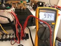
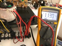
I took some voltage readings pri1<>pri2 and I'm puzzled again (jpegs attached)
mainHot_2_priBlk = 93volt
mainReturn_2_priBlk = 10volts
mainHot_2_priBrn = 9volts
mainReturn_2_priBrn = 113volts
where is the extra 20volts coming from??? I would have similar voltages
as mentioned before,
priBlk_2_priRed = 121volts
priBlk_2_priBrn = 121volts
priBrn_2_priRed = 0volts
I'll report back when I get to 56Volts across the caps for further debug.
Many thanks JM and Andrew for your help!!!
-KF
For Andrew's question:
pri1 mains definitely isolated from pri2
pri2 brn2red connected 1ohm
pri2 brn2blk connected 8ohm
I took some voltage readings pri1<>pri2 and I'm puzzled again (jpegs attached)
mainHot_2_priBlk = 93volt
mainReturn_2_priBlk = 10volts
mainHot_2_priBrn = 9volts
mainReturn_2_priBrn = 113volts
where is the extra 20volts coming from??? I would have similar voltages
as mentioned before,
priBlk_2_priRed = 121volts
priBlk_2_priBrn = 121volts
priBrn_2_priRed = 0volts
I'll report back when I get to 56Volts across the caps for further debug.
Many thanks JM and Andrew for your help!!!
-KF
Attachments


Don't connect the rectifiers until we know how the primaries need to be connected.
I don't understand the test voltages you have so far.
I don't understand the test voltages you have so far.
I don't know what you have measured.pri2 brn2red connected 1ohm
pri2 brn2blk connected 8ohm
You asked for this on Nov.2.
pri1 mains definitely isolated from pri2
Brn is connected to the pri2 red.
Brn is isolated from pri1 (mains) red.
The easy bit first.
Then check again to see if Pri1 is isolated from Pri2. Is Brn separate from BOTH Red, or connected to one Red ?
pri1 mains definitely isolated from pri2
Brn is connected to the pri2 red.
Brn is isolated from pri1 (mains) red.
- Status
- Not open for further replies.
- Home
- Amplifiers
- Power Supplies
- power supply circuit in subwoofer