So You have five wires for primary ? Perhaps 115-0 and 0-115-115+10 (for 240V Australia) but it doesn't make sense...
it is confusing.So You have five wires for primary ? Perhaps 115-0 and 0-115-115+10 (for 240V Australia) but it doesn't make sense...
We know and has been confirmed that there are two isolated primaries.
Pri 1 has Red and Black taps
Pri 2 has Red Brown and Black taps.
Power has been applied to one primary.
Measurements were taken of both primaries.
I don't understand the way the results are being presented.
So You have five wires for primary ? Perhaps 115-0 and 0-115-115+10 (for 240V Australia) but it doesn't make sense...
Please read my post n* 13
No 10V (or any) voltage difference from Red to Brown, both show basically 0 resistance and 0 Volts between them; my strong guess is that Brown is joined to Red through an internal Thermal Fuse like one of these:
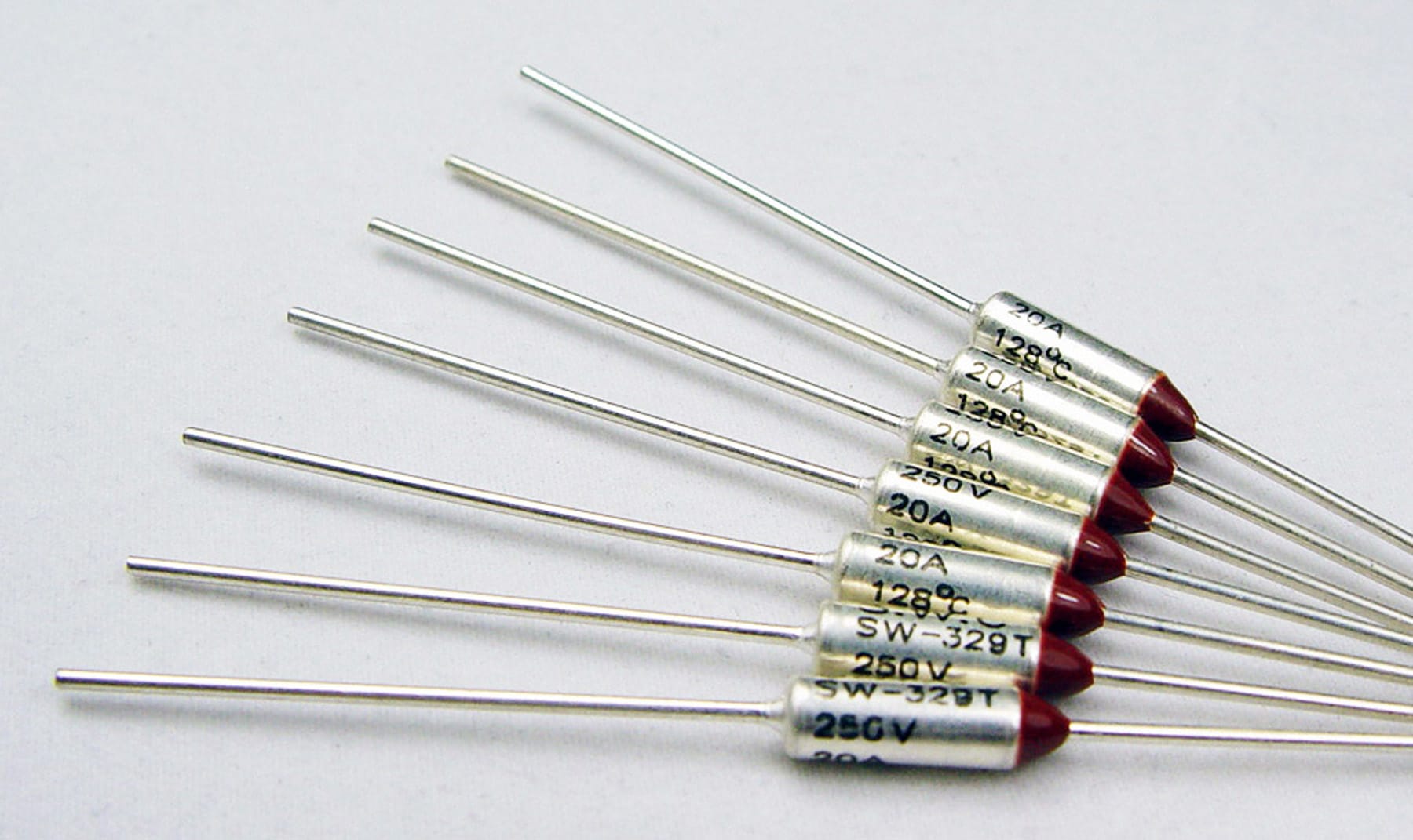
going through the Brown wire first puts the thermal fuse in the path, both for a 115V wiring (as it is now) or series 230V one.
It also allows a repair Tech, in an emergency when the fuse gets open and a new transformer must be ordered from Factory (from anoter Country with all the problems and expense it carries) , then he can bypass it and straight connect to Red and keep the amp running.
On his own responsibility, voids the warranty, etc. , but many times that´s the only possible/practical course of action.
Thanks guys for always preaching safety - currentLimitLamp.jpeg. I used a 250W bulb that measures 4.5ohms from hot plug to the outlet main.
For Andrew's question:
pri1 mains definitely isolated from pri2
pri2 brn2red connected 1ohm
pri2 brn2blk connected 8ohm
I took some voltage readings pri1<>pri2 and I'm puzzled again (jpegs attached)
mainHot_2_priBlk = 93volt
mainReturn_2_priBlk = 10volts
mainHot_2_priBrn = 9volts
mainReturn_2_priBrn = 113volts
where is the extra 20volts coming from??? I would have similar voltages
as mentioned before,
priBlk_2_priRed = 121volts
priBlk_2_priBrn = 121volts
priBrn_2_priRed = 0volts
I'll report back when I get to 56Volts across the caps for further debug.
Many thanks JM and Andrew for your help!!!
-KF
his results do not confirm what you have surmised.Please read my post n* 13
No 10V (or any) voltage difference from Red to Brown, both show basically 0 resistance and 0 Volts between them; my strong guess is that Brown is joined to Red through an internal Thermal Fuse like one of these:
going through the Brown wire first puts the thermal fuse in the path, both for a 115V wiring (as it is now) or series 230V one.
It also allows a repair Tech, in an emergency when the fuse gets open and a new transformer must be ordered from Factory (from anoter Country with all the problems and expense it carries) , then he can bypass it and straight connect to Red and keep the amp running.
On his own responsibility, voids the warranty, etc. , but many times that´s the only possible/practical course of action.
I think we are both confused by how he is presenting his measurements.
Sorry for any confusion in presenting measurements. I'll start with Andrew's quote since it is accurate:
There is a thumbnail on my post from Nov.5 that reads 9.2 volts. Using Andrew's nomenclature:
pri2 Brown to pri1 Red - 9.2volts
pri2 Brown to pri2 Red is 0 volts.
pri2 Brown to pri2 Black is 113volts
At this point, I'm leaning toward using the original wiring configuration to get back to 56volts across the caps connected to the secondary wiring.
Or is there a reason to consider a different wiring configuration for the xformer? Is there a need for any other xformer measurements?
thanks as always Gents
KF
it is confusing.
We know and has been confirmed that there are two isolated primaries.
Pri 1 has Red and Black taps
Pri 2 has Red Brown and Black taps.
Power has been applied to one primary.
Measurements were taken of both primaries.
I don't understand the way the results are being presented.
There is a thumbnail on my post from Nov.5 that reads 9.2 volts. Using Andrew's nomenclature:
pri2 Brown to pri1 Red - 9.2volts
pri2 Brown to pri2 Red is 0 volts.
pri2 Brown to pri2 Black is 113volts
At this point, I'm leaning toward using the original wiring configuration to get back to 56volts across the caps connected to the secondary wiring.
Or is there a reason to consider a different wiring configuration for the xformer? Is there a need for any other xformer measurements?
thanks as always Gents
KF
pri1 is isolated from primary2. There is only leakage current between the isolated primaries due to winding capacitance. Any measurement here is useless.Sorry for any confusion in presenting measurements. I'll start with Andrew's quote since it is accurate:
There is a thumbnail on my post from Nov.5 that reads 9.2 volts. Using Andrew's nomenclature:
pri2 Brown to pri1 Red - 9.2volts
what is the voltage on the other primary?pri2 Brown to pri2 Red is 0 volts.
pri2 Brown to pri2 Black is 113volts
once we know that the two primaries are working and know their phasing, you can connect them in parallel to get the full performance from the transformer.At this point, I'm leaning toward using the original wiring configuration to get back to 56volts across the caps connected to the secondary wiring.
Or is there a reason to consider a different wiring configuration for the xformer? Is there a need for any other xformer measurements?
thanks as always Gents
KF
Then you can check the secondary voltage/s.
voltage on pri1 is 121volts.
secondary:
black to either yellow is 41 volts
yellow to yellow is 82 volts.
secondary:
black to either yellow is 41 volts
yellow to yellow is 82 volts.
Sorry for any confusion in presenting measurements. I'll start with Andrew's quote since it is accurate:
There is a thumbnail on my post from Nov.5 that reads 9.2 volts. Using Andrew's nomenclature:
pri2 Brown to pri1 Red - 9.2volts
pri2 Brown to pri2 Red is 0 volts.
pri2 Brown to pri2 Black is 113volts
At this point, I'm leaning toward using the original wiring configuration to get back to 56volts across the caps connected to the secondary wiring.
Or is there a reason to consider a different wiring configuration for the xformer? Is there a need for any other xformer measurements?
thanks as always Gents
KF
power input from the mains is 121Vac but the voltage from primary 2 is only 113Vac?voltage on pri1 is 121volts.
secondary:
black to either yellow is 41 volts
yellow to yellow is 82 volts.
Something is wrong !
No, that's not what i'm saying. Disregard the 113V and 9.2V measurements as they are only confusing things.
MAINS 121V
pri1red to pri1blk is 121V
pri1brown to pri1red is 0V
secBlack to either secYellow is 41V
xformer seems fine to me. Unless anyone can see a reason not to, I will return to the wiring as suggested by JMFahey so i can get back to 56Volts across the caps spec'd at 80V, 6800uF.
thank everyone for your comments as always.
KF
MAINS 121V
pri1red to pri1blk is 121V
pri1brown to pri1red is 0V
secBlack to either secYellow is 41V
xformer seems fine to me. Unless anyone can see a reason not to, I will return to the wiring as suggested by JMFahey so i can get back to 56Volts across the caps spec'd at 80V, 6800uF.
An easier test:
a) why disconnect red from red if it was factory wiring and to boot the amplifier was *already* showing the proper supply voltages?
As in:
When i turn on the unit, I measure 56Volts across each cap.
KF
Go back to proven working conditions.
b) the amp was *already* working by feeding one side of Mains to Brown, other side to joined Black and both Red joined and taped.
3) what you need to do now is to clean that wiring, junk for now that dangerous dangling yellow cap, you might late replace it but in a better way, connect as I suggested on answer #13 and retest you still have those +/-56V on the caps.
Once confirmed you can go on with the rest of the amplifier.
Of course, since you have been working with the mains wiring and transformer taps, for the first time plug into the lamp bulb limiter, not straight into the wall.
In that case you will measure somewhat less than +/-56V, might go as down as +/-45V , which is normal because the lamp bulb "eats" some voltage.
Well, the transformer label claims 115:36VAC secondaries so no load 37V looks just right, that transformer so far looks in fine shape.
thank everyone for your comments as always.
KF
OK.
The two primaries run at the same voltage.
Tape up or otherwise insulate the Brown primary tapping.
Connect the two reds together.
Connect the two Blacks together. These become your mains input.
Power up via the Mains Bulb Tester and test the input voltage and output voltages again and this re-checks your final transformer wiring.
after that test is successfully completed you can connect your bridge rectifier and power on via the Mains Bulb tester to check your rectifier wiring.
After that is successfully completed you can connect the smoothing capacitors.
Power on via the mains bulb tester check your voltages and ripple voltage.
Only after this is successful do you then connect a load. Again you power on via the mains bulb tester.
OK.
The two primaries run at the same voltage.
Tape up or otherwise insulate the Brown primary tapping.
Connect the two reds together.
Connect the two Blacks together. These become your mains input.
WHY bypass the safety Brown wire?
You are treating it as if it were a user mistake or miswiring while it was put there at the Factory and is printed on the label.
How do you explain that?
And both Red wires were not connected to any switch, fuse or external cable but soldered together and heat shrinked at the Factory.
Explain that.
That you have never seen it and it´s out of your experience area does not mean it´s wrong.
I repeat what I said in posts #13 and #23 , which by the way make sense, while many others (including you) say : "it does not make sense/I don´t understand it/it must be an error" and so on.
The connection you suggest makes the transformer less safe because it bypasses the internal thermal fuse ... unless you think that bypassing fuses is the correct way to handle them 😱
Here, just *one* example out of many showing the internal thermal fuse and its own "extra" wire:
An externally hosted image should be here but it was not working when we last tested it.
cut and paste from Music Electronics Forum, a mostly Technical and Servicing Forum (as opposed to DIYA which is basically hobbyist and home building):
The schematic shows an external fuse and in-rush limiter in the primary wiring as well as an thermal fuse inside the transformer. Have you checked all of these?
You could always dig inside the existing transformer to bypass the thermal fuse if it's blown. But I'd want to know why it blew.
but the thermal fuse Steve refered to is not the same as the system fuse. many transformers have a fuse tucked in between their windings - it opens at a temperature rather than at a current. That is a separate issue from the fuse on the circuit board that responds to current.
The thermal fuse is part of the transformer, it will not be on the schematic. YOu can dig them out and even replace them, but as manufatured, thermal fuses inside the transformers were never intended as a replaceable component. Once in a while some OEM will show a little symbol inside the transformer to indicate its present, but it won;t be called out as a part - just part of the transformer symbol.
and so on.
So again: please do not suggest the OP to bypass a safety device just because you never saw one before.
Thanks.
A Thermal fuse in one primary will open the primary if both are wired in series.
If the user needs to wire the dual primary in parallel to suit 110/120Vac supply, then a thermal fuse in one primary will not cut off the other primary.
If the user needs to wire the dual primary in parallel to suit 110/120Vac supply, then a thermal fuse in one primary will not cut off the other primary.
I have gone back to the factory wiring including the XCAP, and checked the secondary voltages -
either yellow to center tap - 41volts
Then I plugged the secondaries back into the power board and got back to 55.5 volts across each power capacitor.
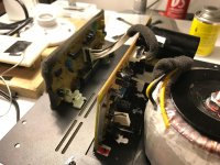
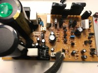
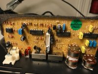
I have included a pics of the power board, preamp board and how they interconnect.
From the User Manual for this subwoofer:
https://www.martinlogan.com/pdf/manuals/manual_mlt2.pdf
"The subwoofer will turn on when it receives an input signal and the LED will turn Green. If no signal is sensed for a period of time, the subwoofer will automatically switch to Standby and the LED will turn Red."
The symtpom is that this LED does not turn on at all, regardless of the presence/absence of an input signal. That's why I began debugging with the xformer and the power caps.
As you can see, the power board has many components on it and I don't have a schematic. I'm really unsure what may be the next steps in debug, especially without a schematic.
As always, thanks for your comments in advance.
-KF
either yellow to center tap - 41volts
Then I plugged the secondaries back into the power board and got back to 55.5 volts across each power capacitor.
I have included a pics of the power board, preamp board and how they interconnect.
From the User Manual for this subwoofer:
https://www.martinlogan.com/pdf/manuals/manual_mlt2.pdf
"The subwoofer will turn on when it receives an input signal and the LED will turn Green. If no signal is sensed for a period of time, the subwoofer will automatically switch to Standby and the LED will turn Red."
The symtpom is that this LED does not turn on at all, regardless of the presence/absence of an input signal. That's why I began debugging with the xformer and the power caps.
As you can see, the power board has many components on it and I don't have a schematic. I'm really unsure what may be the next steps in debug, especially without a schematic.
As always, thanks for your comments in advance.
-KF
Attachments
the temperature sensor is likely to be buried deep so that it monitors maximum temperature which will be in the iron core. i.e. it may be attached to the core before the primary is woumd over it.Just unwrap the isolation and follow the wires...
- Status
- Not open for further replies.
- Home
- Amplifiers
- Power Supplies
- power supply circuit in subwoofer