Have you considered using a separate heater transformer and delay switching the mains to the HV transformer?
boywonder said:Have you considered using a separate heater transformer and delay switching the mains to the HV transformer?
Nope, too much iron. and too cumbersome for so simple purpose, I will use one toroidal power transformer.
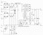
Draft Schematic #2
Hi!
I made a mistake in one of my previous post by attaching schematic with just few parts on the list. Now please take a look at updated version. Not everything is in place yet, but I think you can get basic idea.
Thyristor TH1 can be changed to 2 x zero-cross solid-state relays (like CPC1965G) connected just before high-voltage bridges (if someone wants it).
If anyone could help me finish design it would be very nice.
PS has delayed power on for high-voltage output, and inrush current limiter. The missing part is an automatic protection against short and overload. Anyone ???
Attachments
Why don't you go for a ready to go board from Sophia Electric ?
like this:
http://www.hifitubes.nl/catalog/sophia-electric-power-supply-delay-board-p-106.html
like this:
http://www.hifitubes.nl/catalog/sophia-electric-power-supply-delay-board-p-106.html
This is something I have often thought about for my multi-valve ppp 807 amps(still gathering parts two years down the line, I commisioned some OPTs and the guy decided to give me the cold shoulder, thats another story)
SCRs have the problem of latching on, you can drive them off but thats more circuitry. TRIACs are not really the way for many reasons, although MJ used SS relays on the primary side with no reported ill effects. I am not sure about this as zero crossing is harder to implement than you imagine (plus the problems of constant switching exciting resonances). Especially with a rectified output. Commercial SS relays are designed for resistive loads ie. industrial heating.
Relays can easily make 600VDC but cannot break it without arcing. This will happen on power down when only using one PT.
I think the PS for any reasonably big amp could end up more complicated than the amp itself. Especially when you try to put more than one function into a switching device ie B+ switching on bias failure etc.
If anyone can tell me how to make and break 600Vdc at half an amp (peak of perhaps 50 amps due to the caps) without resorting to a crazy SS SCR design. Please help?.
Cheers Matt.
+ switching on bias failure etc.
If anyone can tell me how to make and break 600Vdc at half an amp (peak of perhaps 50 amps due to the caps) without resorting to a crazy SS SCR design. Please help?.
Cheers Matt.
Have you tried putting a small capacitor across the relay contacts to absorb the sparks ?
This is how they used to do it in car ignition systems.
I had a problem many years ago with popping through the amp when switching record decks on and off, I fixed it with a small capacitor across the switch contacts.
Why don't you go for a ready to go board from Sophia Electric ?
like this:
http://www.hifitubes.nl/catalog/sophia-electric-power-supply-delay-board-p-106.html
I use a PIC microcontroller to do this job with a relay.
Have you tried putting a small capacitor across the relay contacts to absorb the sparks ?
This is how they used to do it in car ignition systems.
I had a problem many years ago with popping through the amp when switching record decks on and off, I fixed it with a small capacitor across the switch contacts.
Correct - and they are switching 12 volts at around 1.5 amps with a back EMF in the region of 2.5kv.
I would also consider a 3w 220k resistor (or similar - figure the value out yourself!) across the contacts to damp the arcing.
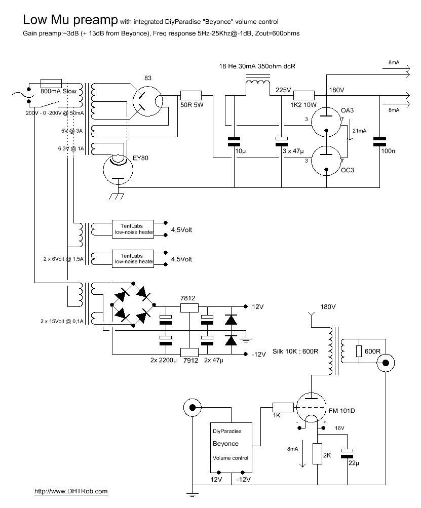
Dutch master DIYer DHTROB, has a cool variation on the theme by using a slow turn-on damper diode (EY80) in the return.
Or you could use a delay board from Sophia Electric.
http://www.sophiaelectric.com/pages/parts/delay_action_board.htm
Or you could use a delay board from Sophia Electric.
http://www.sophiaelectric.com/pages/parts/delay_action_board.htm
Relays can easily make 600VDC but cannot break it without arcing. This will happen on power down when only using one PT.
The relay doesn't actually need to break anything at all... If you place the relay contacts between the PT secondary and the rectifier (the optimal place because you want it to make on AC not DC to prevent migration of contact material) then as long as you have any reservoir capacitance at all on the supply feeding the relay coil there will no longer be anything coming out of the HT secondary by the time the contacts open. The rectifier of course blocks any voltage flowing back from the HT on the reservoir caps.
So apart from a fault condition in the relay drive, as long as everything is working from a single transformer the relay contacts will only ever be called on to make the 600V circuit, never break it.
This works for me on a 400V (KT88 P-P) amp, the relay drops out about 0.5 seconds after power-off and has never shown anything visible from the contacts.
Hope this helps.
Gyro is right.
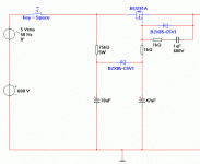
Perhaps you could use my 'electronic choke' wich can be used to have a very slow turn-on.
It's primary design goal was to surpress the ripple, and be useable at a large range of supply voltages.
I guess that changing the value of the 10 microFarad capacitor changes the time to ramp up. Looks nice and simple!
I guess that changing the value of the 10 microFarad capacitor changes the time to ramp up. Looks nice and simple!
Yes, you could also try to change the value of the 75k resistor, but keep in mind it should be able to withstand the full input voltage.
Why do you even need a delayed turn on? You have a valve regulator- that will provide lots of delay, more than enough to eliminate speaker thumps.Hi!
I made a mistake in one of my previous post by attaching schematic with just few parts on the list.
With only 50uF of capacitance after the regulator, there seems little risk of saturation during start-up...
Also, even if you do use a delay circuit do you really need TH1? Can't you use a >600V solid state relay and switch the B+ directly with that? (IC1)
Why do you even need a delayed turn on? You have a valve regulator- that will provide lots of delay, more than enough to eliminate speaker thumps.
With only 50uF of capacitance after the regulator, there seems little risk of saturation during start-up...
Also, even if you do use a delay circuit do you really need TH1? Can't you use a >600V solid state relay and switch the B+ directly with that? (IC1)
Delay need to prevent cathode stripping of 6080 tube of regulated PS. 600V solid-state relays are very expensive, especially for 1+A current. That;s why I would like to use a thyristor.
Have you tried putting a small capacitor across the relay contacts to absorb the sparks ?
This is how they used to do it in car ignition systems.
I had a problem many years ago with popping through the amp when switching record decks on and off, I fixed it with a small capacitor across the switch contacts.
Sorry about getting back so late. I have been writing up a little article on some nixie clocks I am building.
I have tried some small film caps across the contacts, works to an extent.
I really wish to be able to cut the HT dead after the caps. This is the problem, maybe I am just being a perfectionist. I just dont like the idea of 1000uF at 540V going into a failed output valve or transformer (read transformer, expensive).
On the subject of using PICs etc. in a valve amp. This also gives me the jitters. I dont even like using a 555 as a timer. why go to all the trouble of keeping spurious noise etc. out and then introduce a load more?
I know I am way over the top in my thinking but hey KISS.
Cheers Matt.
just re-read.
Gyro, you are dead right, the likelyhood of me (my amps) having a fault and the failsafe tripping before a massive discharge of the PS caps is about zero.
I guess if the failsafe circuit was that fast it would trip on heavy passages anyway.
Looks like a compromise then of failsafe switching on the AC before the rectifiers. Massive crowbar across the caps anyone?. (BANNNNNNG)
Cheers Matt.
having a fault and the failsafe tripping before a massive discharge of the PS caps is about zero.
Cheers Matt.
You could add a extra set of fuses after the capacitors with quick blow fuses.
- Status
- Not open for further replies.
- Home
- Amplifiers
- Tubes / Valves
- Power-On Time Delay Circuit