Hi,
i've built a linear dual power supply to power some symmetrical driver boards. Currently I'm using two boards. A single board makes use of 1 DRV134 buffered with 1 OPA134. Eventually I plan to use this power supply to power 6 of these boards.
The power supply uses the following transformer:
-talema 25 VA
-2x 115 vac, wired in series for 230 vac input
-2x 18 vac secondaries.
-694mA max load per secondary
The first time I tried it out on some real audio signals, i noticed the speakers popping-out a bit when I powered up the boards with my power amplifier already on. A similar kind of popping-in is happening while powering off the drivers with the power amp still on.
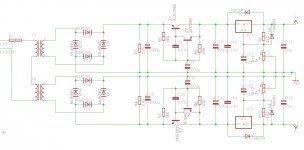
I took a look at the power supply it on my oscilloscope. I connected it to the output voltage supply terminals, after the regulators. Pls. see attached schematic for more info. Both rails of the supply were under a load of 250mA with some high wattage ceramic resistors.
While powering up:
I saw a brief dc offset of about 2 volts, e.g. flat horz. line jumps up from 0 to +2 volts.
While powering down:
I saw a brief dc offset of about -2 volts, e.g. flat horz. line jumps down from 0 to -2 volts.
After about a second, both settle down to 0 volts ac as expected. Both signals are flat or horizontal when measured at line freq, e.g. 50Hz here. At really low dc freq. i saw a surge, not really a spike.
Everything else works as expected, good regulation and extremely low ripple of 1 mV pp.
The pop is really annoying and really exaggerated with the driver boards, which add an additional 6db signal increase. Not to mentions my speakers which I def. don't want to damage. For now, I'm turning the drivers on first before any of the power amps and last when shutting the system off.
Maybe I need to think about adding a soft-start/soft-stop circuit but this is a really small transformer with 25 VA!?
Has anyone else experienced something similar with a low power power supply such as this one?
Cheers,
Chris
i've built a linear dual power supply to power some symmetrical driver boards. Currently I'm using two boards. A single board makes use of 1 DRV134 buffered with 1 OPA134. Eventually I plan to use this power supply to power 6 of these boards.
The power supply uses the following transformer:
-talema 25 VA
-2x 115 vac, wired in series for 230 vac input
-2x 18 vac secondaries.
-694mA max load per secondary
The first time I tried it out on some real audio signals, i noticed the speakers popping-out a bit when I powered up the boards with my power amplifier already on. A similar kind of popping-in is happening while powering off the drivers with the power amp still on.
I took a look at the power supply it on my oscilloscope. I connected it to the output voltage supply terminals, after the regulators. Pls. see attached schematic for more info. Both rails of the supply were under a load of 250mA with some high wattage ceramic resistors.
While powering up:
I saw a brief dc offset of about 2 volts, e.g. flat horz. line jumps up from 0 to +2 volts.
While powering down:
I saw a brief dc offset of about -2 volts, e.g. flat horz. line jumps down from 0 to -2 volts.
After about a second, both settle down to 0 volts ac as expected. Both signals are flat or horizontal when measured at line freq, e.g. 50Hz here. At really low dc freq. i saw a surge, not really a spike.
Everything else works as expected, good regulation and extremely low ripple of 1 mV pp.
The pop is really annoying and really exaggerated with the driver boards, which add an additional 6db signal increase. Not to mentions my speakers which I def. don't want to damage. For now, I'm turning the drivers on first before any of the power amps and last when shutting the system off.
Maybe I need to think about adding a soft-start/soft-stop circuit but this is a really small transformer with 25 VA!?
Has anyone else experienced something similar with a low power power supply such as this one?
Cheers,
Chris
Attachments
Also one other point, completely different from the pop thingie.
In my schematic I have a single ground defined at the end of the rails.
Would it be more advantageous to have two ground points? For example, one tying the rectifiers together at the start of the rails and one at the end?
In this case charging currents from the diodes would have a closer tighter return path or loop separate and away from the supply output ground.
Regards,
Chris
Are you saying that the PSU ground point shifted temporarily by 2V? If so, with respect to what were you measuring it? This is because there is no such thing as voltage, only voltage difference. If two points which you expect to be at the same potential were different then it either means there is a current flowing in a ground conductor or there is a changing magnetic field linking a loop. Both are possible in a power supply.
Hi DF96,
yes i guess this is what I'm saying. It was the zero point that shifted up or down by approx. two volts temporarily. I used an oscilloscope with the ground connection on the ground rail of the psu and the probe first on the positive and then on the negative rails.
It just seemed a little large to me with my limited knowledge.
As already mentioned, i first noticed it when powering up and down my symmetrical amplifier boards. These boards convert an RCA signal to a symmetrical one, e.g. XLR difference output signal for a power amplifier.
The problem is that these voltage swings cause my speakers to move out and in too much.
So i guess a soft start circuit would help for powering up the boards but this wouldn't help the turning off the problem. Here some muting circuit would help in this case.
Regards,
Chris
Last edited:
Sorry, I still don't understand what you were measuring. Are you saying that for a brief while during start-up the supply rails changed from, say, +20V - 0V - -20V to +22V - 0V - -18V ? The 0V rail can't change if you are measuring with respect to the 0V rail.
Im measuring the relative difference.
For example, I'm probing the positive rail. Similar results occur when probing only the negative rail.
I'm trying to visualize what is happening when turning the supply on or off.
After about a second, the psu settles back to 0, e.g. the scope shows a straight horizontal line at 0 volts.
If I mesure at a larger time division, say 50 ms, I see a voltage spike but its not a super sharp spike.
Thanx,
Chris
Hi,
Normally to prevent the thump I used CL60 NTC Thermistors to prevent the inrush current. I like to install it between the rectifiers and the filters capacitors. Some prefer to install it at the primary of the transformer. You can do a search and find out which one suit your taste. Also attached it is a drawing showing the start ground.
Normally to prevent the thump I used CL60 NTC Thermistors to prevent the inrush current. I like to install it between the rectifiers and the filters capacitors. Some prefer to install it at the primary of the transformer. You can do a search and find out which one suit your taste. Also attached it is a drawing showing the start ground.
Attachments
Sorry but this is impossible.For example, I'm probing the positive rail. Similar results occur when probing only the negative rail.
I'm trying to visualize what is happening when turning the supply on or off.
After about a second, the psu settles back to 0, e.g. the scope shows a straight horizontal line at 0 volts.
After you turn it ON, it *must* show either +20V or -20V or whatever each rail has, but not "0V" .😕
When turning OFF, it must show rail voltage (+ or - 20V) becoming zero after a certain time, depending on load and PSU capacitance.
As a side note, I find it weird that you made a complex (considering the minute current consumption involved) 2 tier preregulated PSU ... and you have "thump" problems .¿¿¿???
While a simple 7815/7915 would have been more than enough. ¿¿¿???
Sometimes (as in many times) overcompensating brings instabilities which worsen the problem.
I'm quite sure that a simple R/C/Zener "regulator" would not have this problem, both rails would simply rise smoothly from 0V to Zener voltage , **symmetrically** , and with a time constant (delay) given by R/C values.
Same would happen on turnoff, now RC is defined by C value and load.
Only possible problem on turnoff is that sometimes Op Amps (if you are using them) become "stupid" when rails drop to a couple volts and *may* thump or squeak, but that's an Op Amp problem and will happen with *any* supply.
EDIT: by any chance, are you using this circuit?

With those values?
is this a stage Direct Box or it has some other use?
What signal voltages are we talking about?
Last edited:
Hi everyone,
thanx for the responses, sorry that I have created so much confusion! 🙂
First to DF96:
No coupling, since I'm trying to visualize the "dc" or low freq. changes. But maybe my methods are completely wrong here?? I would expect to see a horizontal line on an oscilloscope anyways, since it only displays ac signals. Or if the signal was changing, i would expect to see it at some dc offset.
To tauro0221:
Yes thanx for the hints, i was thinking about trying out some simple soft-start circuit. Using a variable transformer i set the primary input voltage to 120 which is about half of what we have here and did a power up/down sequence by turning it on/off. As expected, the "spikes were much less.
Now, JMFahey:
If i measure the "dc" rail voltage with a DMM, then they do show valid magnitudes. In my case arround +/- 25 volts. On most oscilloscopes you wouldn't be able to visualize dc signals.
The supply will be used to power some signal diff. preamps or converters that take an RCA signal and output a symmetrical one, e.g. XLR. Since the output signals are low, it is extremely important to have a quiet supply. I have learned that that is not so easy. If the psu were to be used to power something like a power amplifier, I would have used one of the more straight forward designs as can found all over the place. For example, i wouldn't have used any regulation or active RC filtering, bigger filter caps, etc...
The lm317/337's are adjustable and supposedly quieter than the 78/79... regulators.
Yes this is a DI Box and the circuit is quite similar to your depiction, e.g. drv134 with opa134 buffering, 47k input impedance, -6db attenuation, but i have used the non polar output capacitors on the drivers output as recommended in its data sheet for long cables. Also my design didn't use parallel bypass caps with tantals, etc...
See my other posts here for more info about my drv134 boards here:
http://www.diyaudio.com/forums/analog-line-level/228601-balanced-line-driver-drv134-8.html
Except for the thumping problem, they work and sound quite nice.
Cheers everyone,
Chris
Last edited:
If the scope is AC-coupled you will see a spike as the DC rails start up. Exactly what you see will depend on the AC-coupling time constant of the scope and the rise time of the DC supply.
Even with DC-coupling on the scope you may see the regulators going through their start up, and who knows what they will do?
A soft-start circuit may help. The alternative is a muting circuit.
Even with DC-coupling on the scope you may see the regulators going through their start up, and who knows what they will do?
A soft-start circuit may help. The alternative is a muting circuit.
I suspect you are over thinking this, an AC coupled scope will show transients as you power up and down, think about it.... The voltage is changing, how could it not?
Switch the scope to DC coupled and capture both positive and negative startups with the two channels.
I would loose those transistor pre regulators, I don't see the point and until you get the simple version working they just add complexity, odds are that you have PSRR for days at power line frequency plus significant harmonics, add them back in later if you must.
18V is right on the limit, 15V costs you nothing in practise and makes everything run cooler.
For me the thump is probably not power supply related, and is likely more to do with dc conditions on your board taking a while to settle, I don't see a DC path to the input of the DRV134 for example (Yes I know you can get away with this, but I am not seeing any mention of bias currents on the data sheet).
Try lifting one leg of the 1000uF cap, does it still thump (Yes I know it will not pass any signal)?
1000uF into a 10K input? Really? Try shunting pin 4 of the DRV134 with maybe a few K to ground.
Why is the OPA134 set up for a tiny amount of gain? Seems pointless.
Regards, Dan.
Thanks for answering.
I see we have a few small problems here.
I think you did not.
Of course DC implies a horizontal line, but that line sits at the proper "height" above zero, at 23V or whatever you have.
It will definitely not stay at (or return to) zero.
And of course scopes display DC signals on their own; so much so that to see only the AC component you have to filter DC *out* with a series capacitor.
Even further; *if* you connect an AC coupled scope input to some point and apply a "step" voltage to it, (in this case you go from 0V to 23 in an ionstant, and stay there, that's a 23V step), instead of the "square" edge of said stem you'll have a roughly triangular or sawtooth waveform on screen, which does not actually represent the voltage at that rail, at all.
It's just an artifact of a flawed measurement technique.
The slope you will see is not in the rail but comes from the time constant of the input capacitor and scope input impedance.
In fact, they can be used as DC voltmeters.
Since you visually you "count grids" onscreen, the result is not as accurate as a dedicated voltmeter, but they are much used anyway, specially to catch "glitches" , ripple, audio, oscillation, motorboating, etc. on rails.
As an example, when checking power amps I set my scope so one channel shows the rail voltage , so at idle the horizontal line matches the screen top line, and the other goes to the speaker out.
It shows very well both the signal out and how the rail drops under load, and whether the output transistor is working "easily" or is struggling with, say, dropping Hfe or the protection circuit is set way too sensitive, etc.
Just 1 suggestions:
since you have an input buffer anyway, can't you make it have some gain so later stages have less?
It's better to have some gain before sending it on long trips.
That said, I don't know what signal we are talking about, but clearly it's better to send , say, 500mV than 5 mV over the exact same line.
Care to share the real schematic?
It's better to have the actual example than endless guessing 🙂
Good luck 🙂
I see we have a few small problems here.
If you want to visualize DC you must set its input to DC.Hi everyone,
thanx for the responses, sorry that I have created so much confusion! 🙂
First to DF96:
No coupling, since I'm trying to visualize the "dc" or low freq. changes. But maybe my methods are completely wrong here?? I would expect to see a horizontal line on an oscilloscope anyways, since it only displays ac signals. Or if the signal was changing, i would expect to see it at some dc offset.
I think you did not.
Of course DC implies a horizontal line, but that line sits at the proper "height" above zero, at 23V or whatever you have.
It will definitely not stay at (or return to) zero.
And of course scopes display DC signals on their own; so much so that to see only the AC component you have to filter DC *out* with a series capacitor.
Even further; *if* you connect an AC coupled scope input to some point and apply a "step" voltage to it, (in this case you go from 0V to 23 in an ionstant, and stay there, that's a 23V step), instead of the "square" edge of said stem you'll have a roughly triangular or sawtooth waveform on screen, which does not actually represent the voltage at that rail, at all.
It's just an artifact of a flawed measurement technique.
The slope you will see is not in the rail but comes from the time constant of the input capacitor and scope input impedance.
This is to be expectd, if you soften the step edge, you'll see less of it, but still it's a flawed measurement.To tauro0221:
Yes thanx for the hints, i was thinking about trying out some simple soft-start circuit. Using a variable transformer i set the primary input voltage to 120 which is about half of what we have here and did a power up/down sequence by turning it on/off. As expected, the "spikes were much less.
All scopes (except Soundcard based simulations and maybe a **very** cheap one) show AC and DC.Now, JMFahey:
If i measure the "dc" rail voltage with a DMM, then they do show valid magnitudes. In my case arround +/- 25 volts. On most oscilloscopes you wouldn't be able to visualize dc signals.
In fact, they can be used as DC voltmeters.
Since you visually you "count grids" onscreen, the result is not as accurate as a dedicated voltmeter, but they are much used anyway, specially to catch "glitches" , ripple, audio, oscillation, motorboating, etc. on rails.
As an example, when checking power amps I set my scope so one channel shows the rail voltage , so at idle the horizontal line matches the screen top line, and the other goes to the speaker out.
It shows very well both the signal out and how the rail drops under load, and whether the output transistor is working "easily" or is struggling with, say, dropping Hfe or the protection circuit is set way too sensitive, etc.
Agree.The supply will be used to power some signal diff. preamps or converters that take an RCA signal and output a symmetrical one, e.g. XLR. Since the output signals are low, it is extremely important to have a quiet supply. I have learned that that is not so easy. If the psu were to be used to power something like a power amplifier, I would have used one of the more straight forward designs as can found all over the place. For example, i wouldn't have used any regulation or active RC filtering, bigger filter caps, etc...
Just 1 suggestions:
since you have an input buffer anyway, can't you make it have some gain so later stages have less?
It's better to have some gain before sending it on long trips.
That said, I don't know what signal we are talking about, but clearly it's better to send , say, 500mV than 5 mV over the exact same line.
Agree.The lm317/337's are adjustable and supposedly quieter than the 78/79... regulators.
Well, this is an example I found googling the chips you mentioned.Yes this is a DI Box and the circuit is quite similar to your depiction, e.g. drv134 with opa134 buffering, 47k input impedance, -6db attenuation, but i have used the non polar output capacitors on the drivers output as recommended in its data sheet for long cables. Also my design didn't use parallel bypass caps with tantals, etc...
Care to share the real schematic?
It's better to have the actual example than endless guessing 🙂
Good luck 🙂
Hi,
One thing that you must be very careful it is that both -/+ rails voltage must come up equally. Any unbalance would make the op amps to produce a "thump".
What it is the purpose of the T1? You have a 2200uf C8 same as C9 that will slow down the +/- voltage coming up. Do you really need it? I will jump T1 and T3 for a test and see if the "thumps" goes away. I think both LMXXX regulators can the voltage with out the T1 and T3.
T1 and the other transistors between the 2200uF caps implement an "active" RC 1st order filter with corner freq. of around .5 Hz. These made a big difference in filtering out the 50Hz, 100Hz spices and above harmonics of the supply voltage freq. It made it way quieter than w/o them!
This was just an add on, the same popping occurred without them.
Ok, agree with all of you about the visualizing of dc on any scope!
The buffer used with the drv134 is recommended by the data sheet of that chip, e.g. it is recommended to drive the drv134 with a low impedance signal. Its not necessary in my main use case but makes it more utilitarian. Of course buffering allows to change the input impedance or provide better matching for other source impedance. In my case i have an input impedance of 47k.
Actually, my +/- rails are a little bit off relative to one another! I was thinking of this before as a possible issue. For now i have fixed the voltage of the regulators with hard coded resistors. I will add trim pots and set them equally to see if that helps.
Thanx again,
Chris
just to better clarify the filtering in this supply, its called a CRC or pie filter.
In my case its active, which allows me to get a really low cut-off frequency.
It can also be implemented with an inductor and often was in old-school power supplies in tube circuits using a rather large choke.
Cheers,
Chris
In my case its active, which allows me to get a really low cut-off frequency.
It can also be implemented with an inductor and often was in old-school power supplies in tube circuits using a rather large choke.
Cheers,
Chris
Have you checked to see that both power supply rails come up together? Connect scope leads to both the + & - rails with scope ground on the PS ground. Invert the - ps rail signal in the scope and see if both supplies track as they come up to full voltage. If not this is the source of the thump. With all of the R/Cs you have there, this is a real possiblilty.
A different way to check this would be to add the signals in the scope. Or this can be done with 2 EQUAL value resistors. One from the + and one from the - jointed as a summing network. (PS+---R---TP---R----PS-) Any movement from 0 at TP is an offset in the power supply and the reason for the thump.
A different way to check this would be to add the signals in the scope. Or this can be done with 2 EQUAL value resistors. One from the + and one from the - jointed as a summing network. (PS+---R---TP---R----PS-) Any movement from 0 at TP is an offset in the power supply and the reason for the thump.
Last edited:
That would be a pi (not pie) filter, and they are still often seen using ferrite inductors in high frequency supression applications, I scatter the things all over the shop when designing radio gear.
I still think you problem is most likely waiting for the dc operating point to stabilise and nothing to do with your power supply, and that the biggie is possibly the driver input bias current. Pull that pin to ground with a few K and I suspect most of the noise will vanish.
I was not arguing with the presence of the buffer amplifier, but was questioning why it had a tiny amount of voltage gain, I just don't see the point.
I still think the sheer size of that NP cap is overkill, and that for this kind of thing a simple 78/79 series regulator pair are usually quite quiet enough to not be the limiting factor in the system as a whole.
Regards, Dan.
Have you checked to see that both power supply rails come up together? Connect scope leads to both the + & - rails with scope ground on the PS ground. Invert the - ps rail signal in the scope and see if both supplies track as they come up to full voltage. If not this is the source of the thump. With all of the R/Cs you have there, this is a real possiblilty.
A different way to check this would be to add the signals in the scope. Or this can be done with 2 EQUAL value resistors. One from the + and one from the - jointed as a summing network. (PS+---R---TP---R----PS-) Any movement from 0 at TP is an offset in the power supply and the reason for the thump.
Since i have a two channel scope and can invert either signal, i will def. try out your first suggestion. Won't be able to get to it for a couple of weeks but i will post the results later. Thanx🙂
That would be a pi (not pie) filter, and they are still often seen using ferrite inductors in high frequency supression applications, I scatter the things all over the shop when designing radio gear.
I still think you problem is most likely waiting for the dc operating point to stabilise and nothing to do with your power supply, and that the biggie is possibly the driver input bias current. Pull that pin to ground with a few K and I suspect most of the noise will vanish.
I was not arguing with the presence of the buffer amplifier, but was questioning why it had a tiny amount of voltage gain, I just don't see the point.
I still think the sheer size of that NP cap is overkill, and that for this kind of thing a simple 78/79 series regulator pair are usually quite quiet enough to not be the limiting factor in the system as a whole.
Regards, Dan.
Which pin are you talking about?, pin4 of the drv134, e.g. its signal input?
The buffer, simply provides a low impedance signal for the drv134, again its a recommendation in the TI's drv134 data sheet.
Regards,
Chris
- Status
- Not open for further replies.
- Home
- Amplifiers
- Power Supplies
- power on/off dc surge