Hi,
Another way to see both channel is see if your scope have single trigger. Trigger in channel one and as soon the channel one signal goes high the scope will give you a single shot display of what happening at the power ON.
Another way to see both channel is see if your scope have single trigger. Trigger in channel one and as soon the channel one signal goes high the scope will give you a single shot display of what happening at the power ON.
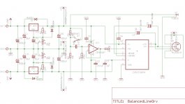
Ahh, sorry, I was commenting on jmfaheys circuit diagram, but yea if you are capacitor coupling between stages then a resistor from pin 4 on the DRV134 to ground, maybe 2k2 or such.
That circuit had a tiny amount of gain around the buffer amp for no obvious reason, I have not seen your version.
Regards, Dan.
That circuit had a tiny amount of gain around the buffer amp for no obvious reason, I have not seen your version.
Regards, Dan.
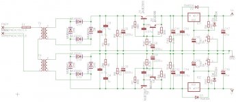
Have you checked to see that both power supply rails come up together? Connect scope leads to both the + & - rails with scope ground on the PS ground. Invert the - ps rail signal in the scope and see if both supplies track as they come up to full voltage. If not this is the source of the thump. With all of the R/Cs you have there, this is a real possiblilty.
A different way to check this would be to add the signals in the scope. Or this can be done with 2 EQUAL value resistors. One from the + and one from the - jointed as a summing network. (PS+---R---TP---R----PS-) Any movement from 0 at TP is an offset in the power supply and the reason for the thump.
Hi Bzed, i made the measurements... The negative rail is shooting down to about -13 volts briefly while the positive rail only changes by approx. + 2 volts.
This only happens when the supply is initially turned on or when the caps are bled out. If I turn off and on again quickly s.th. the caps are not fully discharged, then both rails change by about +/- 2 volts pretty symmetrically.
I measured this both with the voltage regulators and then w/o them. Both produced similar results.
When first putting this psu together i accidentally had a diode short and it smoked just a little, so i replaced all of the bridge diodes but maybe the transformer was somehow damaged by that. I meas. the dc resistance of both its primaries and secondaries and they were according to specs.
I will desolder the transformer and measure both of its secondaries later to see how they look
Cheers,
Chris
I've tested the transformer now after isolating it from the circuit.
First test was w/o any load on the secondaries.
-both ac voltages on both secondaries come up identically
Noticed that the wave crests appeared a little flat or clipped.
This seems to be normal, after comparing it to another diff. transformer i have never used!
Second test was with about 260 mA load per secondary, which is about 1/2 of the max load.
-both ac voltages on both secondaries come up identically
So its not the transformer or diodes. Even checked the ESR of the filter caps, they all seem ok.
So it appears as if the only thing it can be now is some cold solder joint on the psu board.
I have made a lot of adaptions here to test out various filtering techniques, etc..., so i will try soldering up a new board and as i go along i will measure the startup voltages of each rail before adding additional parts.
Cheers,
Chris
- Status
- Not open for further replies.