OMG he said that he worked in nuclear physics and claimed that the vacuum is a resistor or like a resistor, doesn't matter ... I read that after my post 
Last edited:
Sarcastic, perhaps you could make the effort to learn rather than assume or get a notion of how things work based on some unfortunately flawed view. I'm sure there may be simpler texts to learn from, but if you have a physics background then the 1962 RCA Electron Tube Design book is an excellent reference, especially the Space Current section for what you appear to be missing an understanding of. (File:RCA Electron Tube Design 1962.djvu - Wikimedia Commons)
Thank you. I will read...
The RCA book is available at Pete Millett's amazing collection:
http://www.tubebooks.org/Books/Atwood/RCA 1962 Electron Tube Design.pdf
One of many found here:
Technical books online
How do we thank this guy?
http://www.tubebooks.org/Books/Atwood/RCA 1962 Electron Tube Design.pdf
One of many found here:
Technical books online
How do we thank this guy?
For a good understanding of phenomena , in a resistor it is the same ,
It's not even remotely like a resistor.
Resistors are not polarised and are not semiconductors.
The whole point about the whole argument, the cathode is heated by a heater.
Say approx 5W of power (in the case of 807).
If the electrons could heat the anode themselves, how come they are only being given about 2-3W of power to be able to do it for a 25W anode?
No,- in reality the cathode is at 0 volts, and the cathode coating emits enough electrons to hit theoretic saturation with approx 100V and 400m/a.
The main advantage with the beam tetrode is acceleration of the electrons via the screen grid, which is in fact the REAL anode being accelerated enough to strike the virtual anode on the other side of the beam directing plates.
This is of course why the anode can continue to conduct loads of current despite the anode only being at 100V while the screen is at 300V.
It was in fact the 6L6 and 807 which served as the main test bed for this behaviour, particularly aligned grids to increase efficiency via reduced screen current.
Of course electron flux from the cathode is a proxy for current flowing from the anode to the cathode, but what makes the anode dissipation is not the electron arrival, but the current flow v voltage drop across the gap.
Ok. For my own understanding.
As I understand, electrons are "boiled off" of the cathode and surround it as a "space charge". With no voltage on the anode, no electrons are attracted to it. If there is a voltage on the plate, the electrons starts from roughly zero velocity and accelerates towards the plate. The electron strikes the plate giving up kinetic energy which makes the plate hot. Kind of like how shot peaning or sandblasting tends to heat the work. Or how a Tapcon gets hot when you drive it into the wall.
I also see the triode as a voltage controlled resistance, so in theory, if you could put an own meter from cathode to plate without blowing it up, it would measure a resistance.
All I know is if there is 0V on a cathode, 300V on an anode, and 60mA of current flowing, that device is eating 18W. Ohm's law, right? If you could measure the voltage halfway between plate and cathode wouldn't it be roughly 1/2 B+?
Member
Joined 2009
Paid Member
A few good bits there, but many are ‘no’.
E.g. the electric field between plate and cathode is certainly non-linear.
E.g. Ohms law in it’s simple form doesn’t have validity in many of the ways posters have tried to apply it.
E.g. the electric field between plate and cathode is certainly non-linear.
E.g. Ohms law in it’s simple form doesn’t have validity in many of the ways posters have tried to apply it.
Member
Joined 2009
Paid Member
what makes the anode dissipation is not the electron arrival,
You still insist on this? But….it is exactly their arrival and deceleration on impact with the solid plate that is the cause of the heating, it is the process where they give up the energy gained from traversing the vacuum cathode-plate electric field and transfer it into heating of the anode.
Whilst we don’t like this heat in our amplifier, I have used this effect to advantage many years ago in an e-beam evaporator for depositing material onto GaAs wafers.
Last edited:
At heart its very simple, an electron acquires kinetic energy equal to eV, and then dissipate that energy into the target electrode, releasing eV there as heat (and a small fraction of secondary emission, X-rays, etc).
V is the potential difference, e is charge on the electron.
Thus the power = IV, since the electron flux = I/e electrons/s, so the energy per second is (I/e)eV.
Very well explained, and absolutely correct, in my opinion. I like your gravitational analogy too, and your observation that while one could work out the velocity of the balls at impact, it is not necessary for working out the heating.
Last edited:
The main advantage with the beam tetrode is acceleration of the electrons via the screen grid, which is in fact the REAL anode being accelerated enough to strike the virtual anode on the other side of the beam directing plates.
This is of course why the anode can continue to conduct loads of current despite the anode only being at 100V while the screen is at 300V.
In a beam tetrode electrons are accelerated by g2. Between g2 and beam plate electric field is reversed and electrons are de-accelerated. After beam plate electrons are accelerated again by anode. Higher Va, higher electron speed hitting the anode, more heat at anode (and vice versa).
Yes, thanks to g2 beam tetrode can pass same current at lower Va than triode. But that also means lower electron speed hitting the anode, giving lower dissipation and lower resistance.
So, difference between triode and beam tetrode is actually a proof that anode is heated by kinetic energy of electrons, not other way around.
Just thinking aloud:
* IF vacuum were a resistor, even better THE significant resistor, the heat dissipation would be along the path.
Then dissipation would be in vacuum, vacuum would heat up, anode would remain cold.
Clearly this is an absurd explanation.
* IF plate were a resistor where all those Watts are dissipated, then it would show ... ummmmm ..... **resistance** (duh!) .... which of course would be measurable.
And in fact is: you apply meter probes between any 2 points of a metal plate, you´ll get fractions of an Ohm.
Even lower if you measure between 2 matching points, one inside, one outside, along the metal thickness which is also the presumed line of travel the electron was following.
Now you calculate the power dissipation here: I squared times that Plate resistance: dissipation will be VERY low, microwatts, so that is NOT the Plate heating mechanism either.
* once you discard the "Ohmic" explanation, all that remains is electronic impact energy being converted into heat, what else?
And *where* does that happen?: at Plate inner surface, where Electrons arrive.
* calling G2 "the real Anode" is, at best, a poorly applied oversimplification.
Truth is **any** electrode with voltage more positive than Cathode is **AN** Anode.
That we call electrodes other than Cathode by different names: Plate, Screen, Grid, etc. is just a simplification, or better said a practical way to describe the job we expect from them in our everyday circuits, but what really matters is voltage difference between each of them and cathode.
As a dual-use example, usually we apply negative voltage to grid (G1) and so it is not an Anode, but as soon as we turn it positive, it will start attracting electrons and passing current, meeting both Anode definitions.
So much so that now we have a *Diode*, where Cathode is Cathode and Anode is "Grid", go figure.
As of kodabmx´s:
Only you wouldn´t use a conventional meter which takes some current, but an electrostatic meter, typically a very thin electrically charged gold leaf.

Electrometer - Wikipedia
Electroscope - Wikipedia
* IF vacuum were a resistor, even better THE significant resistor, the heat dissipation would be along the path.
Then dissipation would be in vacuum, vacuum would heat up, anode would remain cold.
Clearly this is an absurd explanation.
* IF plate were a resistor where all those Watts are dissipated, then it would show ... ummmmm ..... **resistance** (duh!) .... which of course would be measurable.
And in fact is: you apply meter probes between any 2 points of a metal plate, you´ll get fractions of an Ohm.
Even lower if you measure between 2 matching points, one inside, one outside, along the metal thickness which is also the presumed line of travel the electron was following.
Now you calculate the power dissipation here: I squared times that Plate resistance: dissipation will be VERY low, microwatts, so that is NOT the Plate heating mechanism either.
* once you discard the "Ohmic" explanation, all that remains is electronic impact energy being converted into heat, what else?
And *where* does that happen?: at Plate inner surface, where Electrons arrive.
* calling G2 "the real Anode" is, at best, a poorly applied oversimplification.
Truth is **any** electrode with voltage more positive than Cathode is **AN** Anode.
That we call electrodes other than Cathode by different names: Plate, Screen, Grid, etc. is just a simplification, or better said a practical way to describe the job we expect from them in our everyday circuits, but what really matters is voltage difference between each of them and cathode.
As a dual-use example, usually we apply negative voltage to grid (G1) and so it is not an Anode, but as soon as we turn it positive, it will start attracting electrons and passing current, meeting both Anode definitions.
So much so that now we have a *Diode*, where Cathode is Cathode and Anode is "Grid", go figure.
As of kodabmx´s:
Yes, definitely.All I know is if there is 0V on a cathode, 300V on an anode, and 60mA of current flowing, that device is eating 18W. Ohm's law, right? If you could measure the voltage halfway between plate and cathode wouldn't it be roughly 1/2 B+?
Only you wouldn´t use a conventional meter which takes some current, but an electrostatic meter, typically a very thin electrically charged gold leaf.
Electrometer - Wikipedia
Electroscope - Wikipedia
Last edited:
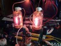
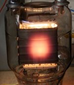
Crank things up enough and you will see where the dissipation is. The plate gets red hot. The vacuum between the cathode and plate does not.
Do this long enough and there will not be a vacuum left between the cathode and plate due to ions and other trapped impurities being boiled off the plate. Once this happens the non vacuum in that space may ionize, at which point the ionized cloud will dissipate heat getting hot while the plate cools down.
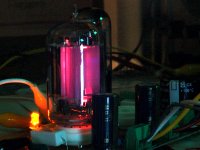
Note the stream of glowing ions coming from the hole burned through the plate in a rectifier tube (last picture). The well used tube had the hole when I found it. It tested good and did actually work in an amplifier. I did not trust it, so I "tested" it a bit beyond it's ratings.....until it no longer worked.
Do this long enough and there will not be a vacuum left between the cathode and plate due to ions and other trapped impurities being boiled off the plate. Once this happens the non vacuum in that space may ionize, at which point the ionized cloud will dissipate heat getting hot while the plate cools down.
Note the stream of glowing ions coming from the hole burned through the plate in a rectifier tube (last picture). The well used tube had the hole when I found it. It tested good and did actually work in an amplifier. I did not trust it, so I "tested" it a bit beyond it's ratings.....until it no longer worked.
Attachments
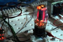
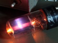
Tubelab, your 2nd photo is a nice example of which opposite side 'faces' of a typical power tube get hotter, and uses the extended plate structure seam as a form of heatsink fin to allow easier heat radiation at an angle away from perpendicular to the face. Just goes to show how output stage valves preferably don't have those 'faces' pointing towards each other.
As I stated previously, the hole was in it when I got it. The tube was a 6AX4 I think and it came in a box full of assorted used tubes that I got for cheap or free at a hamfest. The usual cause of something like this is a dead horizontal sweep (line output) tube (K to G1 short) or loss of drive to the output tube resulting in a full "ON" condition.
Small tubes like the 6AQ5 will indeed crater the glass then "sucking air" as the glass is very close to the plate. I once found a large sweep tube in a TV set with the glass nearly perfectly formed around the internals before the circuit breaker popped. Unfortunately it also soldered itself into the socket and I broke it trying to remove it. Attempts to intentionally do this have all failed, but I did get a 6AS7G hot and gassy enough to make the glass bulge outward before it "blew air" and died.
The trick, run positive grid bias and a high enough plate current to get one plate glowing real hot. Apply a big power supply between it and the other plate with the negative end on the glowing plate. Crank up the electricity until a few AMPS are flowing from hot plate to the now hotter plate. Plasma balls, lightning bolts and other cool (OK HOT) fireworks will result. Current limiting, a ballast, or both are your friends here and needed to avoid an exploding tube. Do not do this indoors or near any flammable material.
The trick, . . . . . . . I blow stuff up so that you don't have to.
Why would we want to? Reading your description of how you did it is more fun!

This fun thread has been very educational.That we call electrodes other than Cathode by different names: Plate, Screen, Grid, etc. is just a simplification, or better said a practical way to describe the job we expect from them in our everyday circuits, but what really matters is voltage difference between each of them and cathode.
It demonstrates how when you throw a rock in a pool to observe the ripples, and watch them spread out, the behaviour is absolutely predictable.
The trends are all well inside the statistical bell curve.
The number of members here who immediately revert to ad hominem & flaming was confirmed, while the other trend towards the "booky" RTFM - here "I can recommend a good book" (snooty) was another.
There were one or two other trends which were at the outside end of the spectrum, professional respectful and correct, Wavebourn as usual and Tube lab.
Confirms online behavioural psychology very well especially in the "cliquey" end. 🙄
Not to you since you absolutely refuse the very BEST advice:This fun thread has been very educational.
"I can recommend a good book"
So we are saying "2+2=4" (against your beliefs) only because "we" have a Psychological problem?Confirms online behavioural psychology very well
Funny, specially coming from you.
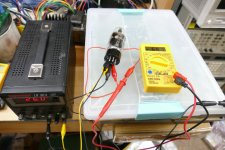
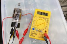
I propose a simple experiment that anyone here should be able to do. You need a vacuum tube, a power supply capable of powering it's heater, and a cheap multimeter.
Connect the power supply to the heater and adjust it to apply the rated voltage to the heater.
Connect a meter lead to the cathode, and the other meter lead to the element closest to the cathode. This would be the grid in a triode, G1 in a pentode, or the plate in a rectifier.
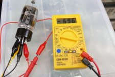
Set the meter to read DC voltage and you should see a small negative voltage on the tube's grid / plate. In my case I'm using a 26HU5 sweep tube and I get reading of NEGATIVE 696 millivolts.
Set the meter to DC current and you will see a small current flow even though there are NO voltages applied to any of the tube's active elements. In my case I see NEGATIVE 60.8 microamps.
This voltage and current is caused by electrons from the cathode striking the element and being collected by it. The meter's internal resistance provide a path for current flow for the collected electrons back to the cathode. This is the basis for "grid leak bias" seen in very old vacuum tube electronics.
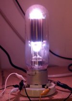
The big 833A tube seen glowing in my previous pictures has a 100 watt heater (10V at 10A). It blasts out enough electrons that a connecting a set of headphones from the plate or grid to the heater will produce a fairly loud 60 Hz hum WITHOUT any plate or grid voltage.
For any given set of operating conditions across a tube there is an associated resistance from cathode to plate, often called Rp. It can not simply be measured with an ohmeter due to the electron flow induced voltage. One can calculate a value from the applied voltage and current flow. It is not a linear function.
The heat in the plate of a tube is primarily from two sources, direct electron bombardment, and radiated heat from the heater inside the cathode. The sweep tube in my picture has a 15 watt heater. The plate and the glass will get quite hot with only heater voltage applied. A common IR thermometer will not get a good reading of the plate temperature due to poor IR transmission through the glass.
Connect the power supply to the heater and adjust it to apply the rated voltage to the heater.
Connect a meter lead to the cathode, and the other meter lead to the element closest to the cathode. This would be the grid in a triode, G1 in a pentode, or the plate in a rectifier.
Set the meter to read DC voltage and you should see a small negative voltage on the tube's grid / plate. In my case I'm using a 26HU5 sweep tube and I get reading of NEGATIVE 696 millivolts.
Set the meter to DC current and you will see a small current flow even though there are NO voltages applied to any of the tube's active elements. In my case I see NEGATIVE 60.8 microamps.
This voltage and current is caused by electrons from the cathode striking the element and being collected by it. The meter's internal resistance provide a path for current flow for the collected electrons back to the cathode. This is the basis for "grid leak bias" seen in very old vacuum tube electronics.
The big 833A tube seen glowing in my previous pictures has a 100 watt heater (10V at 10A). It blasts out enough electrons that a connecting a set of headphones from the plate or grid to the heater will produce a fairly loud 60 Hz hum WITHOUT any plate or grid voltage.
For any given set of operating conditions across a tube there is an associated resistance from cathode to plate, often called Rp. It can not simply be measured with an ohmeter due to the electron flow induced voltage. One can calculate a value from the applied voltage and current flow. It is not a linear function.
The heat in the plate of a tube is primarily from two sources, direct electron bombardment, and radiated heat from the heater inside the cathode. The sweep tube in my picture has a 15 watt heater. The plate and the glass will get quite hot with only heater voltage applied. A common IR thermometer will not get a good reading of the plate temperature due to poor IR transmission through the glass.
Attachments
Sadly for you I worked in nuclear physics, and I can assure you, the electrons simply do NOT have enough mass or energy inside a valve to heat the anode.
In a sychrotron we accelerate particles to MeV, then we are talking, when it hits the target.
We can get some serious joules of energy to knock bits of atoms off.
The problem with your inability to understand the basic physics is that the heat CANNOT come from the electrons, it can only come from an impedance. (which is simply a conversion of a resistance in dynamic terms).
Ie, if you put 300V on the anode of a 12AX7 with the anode impedance of 62K you get 4.8m/a current which equates to 1.5W.
Where do the watts come from?
By the simple fact the anode looks like a whopping great 2W resistor to a DC supply.
Nothing to do with the tiny number of electrons swopping places, it's simple current and voltage regulated by the space between the different electrodes.
...
It's not the electrons heat it up, it's the voltage drop x the current, same as a normal valve.
If the anode current is 4.8mA then that means about 3 x 10^16 electrons are hitting the anode every second (since each electron carries about 1.6 x 10^(-19) Coulombs of charge). 3 x 10^16 electrons per second is not exactly "tiny"! So indeed the impact of each individual electron on the anode dumps a very small amount of energy, namely e x V which is about 5 x 10^(-17) Joules. But with 3 x 10^(16) of them arriving per second, that works out to a total of about 1.5 Joules per second, which is of course the 1.5W of dissipation implied by the calculation of P = I x V.
It was all very nicely explained by Mark Tilllotson in his post #36. I/e electrons arrive per second on the anode, each with a kinetic energy of e x V, hence implying a total energy per second of (I/e) x (e x V) = I x V, which is the power P = I x V. Almost all of this is dumped as heat in the anode.
One problem with your proposed "explanation" is that it doesn't really explain anything at all; it is really just an almost tautologous statement that if a two-terminal "black box" has a current I passing through it and a voltage drop V across it, then a power P= I x V is dissipated in it. But it doesn't explain *where* the power is being dissipated, nor what the mechanism is. These were the questions the OP was asking. As Mark and some others have said, the proper microscopic understanding of what is going on involves appreciating that the electrons (a lot of them!) are accelerated towards the anode from the cathode, and they deposit almost all their kinetic energy as heat when they slam into the anode.
- Home
- Amplifiers
- Tubes / Valves
- Power dissipation in tubes, where is it occurring?