Andrew, hi
Many thanks, the green and yellow was an alternative Chassis GND but at the moment its not connected to anything and was not as good as the local connection near the mains in. So I will at some stage remove
The other think I did notice was the double insulated 500 version (with inbuilt pre amps) have the mains earth cable tracks through the amps and just connecting to the speaker out 0v via a cap, so I might try this as well (it has a 100nf 400v MKT cap) I did see this noted as an option for the speaker out terminals to have a cap to earth as an option reducing RFI.
How are the secondary wires from the transformer to the board arranged? Is there a big loop area between the centre-tap and the other two ends?
Probably best to remove the centre-taps from the current location on the board, and move it closer to the ground point at the top of the board rather than through a wire from below.
Looking at the pictures, you may want to shorten the secondary leads, and then tightly twist the secondary wires (including centre-tap wires) before connecting to the rectifier and board ground. I think the secondary wires are radiating the large 50 Hz component.

Andrew Thanks
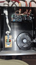
The rough layout from above (I used an old top image so please ignore the black cable to the pot), the underside is a flipped image so you can see where the locations are. The transformer outputs go straight down to the 4 tabs on the board with the secondaries then going via 15A fuses to the rectifier.
Top pic - Yellow shows the rough location of the transformer 0v cable, green show the centre 0v/GND pad and the location of the speaker out cable thin green line. The brown and dark blue the AC mains and the light blue the signal in 0v
If I went in between the four caps for the transformer GND and not down and across underneath the journey is similar ? Looking at the brown cable I soldered (bottom picture left hand side top the thicker cable taking the transformer secondary 0v to the 'T') it would be better to move it away from the rectifier and more direct ?
What was the amp like when taken out of the chassis and mounted on a wooden board . Still the same amount of hiss ?
did you think you re-arranged the grounding with those wires ?
2 issues here:-
first, the grounding is defined by pcb tracks, which you have not cut, so placing wires here and there has no effect
second, re-ordering of the grounding must follow some worthwhile arrangement as per post 95
--------------------------------------------------------------------------------------------------------------------------
i will post a picture of something for you to try later.
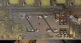
ok, here is my suggestion, which may or maynot have been implimented by your mods already.
the caps currents are a-b and c-d (since there are 2 pairs), and no 0v must be taken from this area.
there are two ground take off routes, e and f, which should be ok to serve the amp
my suggestion is to solder/connect the txmr "centre tap" wire(s) to point x and leave everything else as stock.
the caps currents are a-b and c-d (since there are 2 pairs), and no 0v must be taken from this area.
there are two ground take off routes, e and f, which should be ok to serve the amp
my suggestion is to solder/connect the txmr "centre tap" wire(s) to point x and leave everything else as stock.
Attachments
Are you sure this amp is not oscillating?
since the "mods" so far have been fruitless, this aspect should be checked out with a scope
I will have a lookout REW as I think it has a scope simulation, I don't own a scope unfortunately
More homework on testing the non modified chassis this time on a piece of wood with the transformer some distance away, with wires and cabling in different locations. The results for the non modified and uncased version were consistent and a little different to the cased version. The non cased and unmodified version is noisier by measurement and listening
Connected up in the normal way the Blue trace is the uncased unmodified version, the green is the cased and modified version and the pink the target of the 500


Connected up in the normal way the Blue trace is the uncased unmodified version, the green is the cased and modified version and the pink the target of the 500
I have tried both transformers, the coil is under a metal tray and using either transformer remotely measures the same as open the unit
Looks like the chaining of the grounding might have improved things a little, it also looks like both units (one stock and one with the moved GND points) are not materially affected by being mounted in the chassis with transformer close or off the chassis with the transformer some distance away
Un-modified base on and off the chassis

Modified base on and off the chassis

Un-modified base on and off the chassis
Modified base on and off the chassis
Your trace above is not bad. For the 50 Hz spike please try the following:
Clip your heatsink and metal work to the metal case of your A-D. Make sure all the metalwork connections measure close 0 ohms. This sometimes improves 50 Hz rejection dramatically on measurement setups because it ensures any common mode voltage between the metalwork and the electronics is at 0 V and therefore not able couple into the electronics through either poor CMRR (a typical unbalanced interconnect problem) or via capacitive coupling into hi-Z nodes in the amp circuit (a less common phenomena).
Clip your heatsink and metal work to the metal case of your A-D. Make sure all the metalwork connections measure close 0 ohms. This sometimes improves 50 Hz rejection dramatically on measurement setups because it ensures any common mode voltage between the metalwork and the electronics is at 0 V and therefore not able couple into the electronics through either poor CMRR (a typical unbalanced interconnect problem) or via capacitive coupling into hi-Z nodes in the amp circuit (a less common phenomena).
Looks like the chaining of the grounding might have improved things a little, it also looks like both units (one stock and one with the moved GND points) are not materially affected by being mounted in the chassis with transformer close or off the chassis with the transformer some distance away
Un-modified base on and off the chassis
View attachment 1434342
Modified base on and off the chassis
View attachment 1434343
I'm from Germany. Here, it's possible to build protection class 2 (protective insulation), which means that the insulation is so good that grounding the case is unnecessary. Personally, I always build this way. I have no grounding or chassis ground. I never experience any hum or noise.
Attachments
Anodized aluminum is unsuitable for grounded amplifier enclosures. The resistance becomes too high, and the enclosure components conduct electricity poorly. Steel is significantly better for grounded enclosures.Your trace above is not bad. For the 50 Hz spike please try the following:
Clip your heatsink and metal work to the metal case of your A-D. Make sure all the metalwork connections measure close 0 ohms. This sometimes improves 50 Hz rejection dramatically on measurement setups because it ensures any common mode voltage between the metalwork and the electronics is at 0 V and therefore not able couple into the electronics through either poor CMRR (a typical unbalanced interconnect problem) or via capacitive coupling into hi-Z nodes in the amp circuit (a less common phenomena).
DIY officially can not be class II, DIYing a class I device to class II also is questionable. Having the OP disconnecting PE is not the way to go as PE is for safety and not the cause of the problem.
Between all the attention diverting graphs and measurements this was concluded:
Between all the attention diverting graphs and measurements this was concluded:
I have managed to remove 99% of the buzz by trying capacitors as the link from Chassis to GND when the chassis earth connection is in place. With a number of .1uf variants the TDK ceramic was the best. If I add a resistor 20 Ohms or so it's fine as well with both attached.
Last edited:
- Home
- Amplifiers
- Solid State
- Power amplifier noise from chassis EARTH - any ideas?