Hello, I found this power amplifier in a book; and I want to know a little about it, before make it.
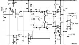
What is R7 - R8 - C8 doing?
What is R13 - R11 - C7 doing?
PD: I write in spanish too, because I dont speak very well in english. Thanks!
In Spanish:
Hola, encontré este amplificador en una revista, y voy a armarlo, pero antes de eso me gustaría aprender un poco acerca de él.
¿Que función cumple R7 - R8 - C8?
¿Que función cumple R13 - R11 - C7?
PD: Perdón por escribir en los dos idiomas, pero no hablo mucho inglés, y por temor a equivocarme y por las dudas lo agrego. Gracias!
Attachments
aguantesoda said:What is R7 - R8 - C8 doing?
What is R13 - R11 - C7 doing?
Those are "bootstraps". Consider them as constant current sources. AC bypassing R8 and R13 will keep the DC voltage drop over the resistors constant regardless of signal voltage swing. Constant voltage drop over constant resistance results to constant current. The voltage amplifier operates in more linear manner when it's loaded by a constant current source.
R13-R11-C7 is an addition I'm a bit unfamilar with. Perhaps someone can explain the difference between this and the conventional arrangement?
Strange, it seems to be another bootstrap
A double bootstrapp.....symetrical and complementary...hehe....very different.
Do you have more informs?
Someone had constructed?
regards,
Carlos
A double bootstrapp.....symetrical and complementary...hehe....very different.
Do you have more informs?
Someone had constructed?
regards,
Carlos
I have seen some guitar/bass amplifiers from the 70's that used this symmetric bootstrapping arrangement. SPICE sim shows that in comparison to conventional topology this one can swing about 1 volt closer to negative rail (which is not much). Clipping of the negative rail also introduces a strange "glitch" so this symmetric configuration doesn't look too stable either. The arrangement never seemed to catch success so I wonder does it have any significant benefits over the conventional one with single bootstrap/active CCS? Are there any particular reasons why it isn't used that much?
The adjustment suggested, adjusting the threshold of the over current protection
Adjustment suggested into the text was made over 2 ohms load...and made to allow the protective transistors to hold maximum of 7.5 Volts over 2 ohms in the output...this is a problem.
Was made to protect the output, but will disturb hardly sonics.
This will protect, as a single transistor is used into the output, ...a single pair...but will kill all musical dinamics when using real speakers.
There are many speakers, that despite having 8 ohms specified, that has very lower values, depending on frequencies..sometimes 4 ohms and lower impedances can be found....in this moment the over current protection will start to limit.... say, into frequencies where a deep of impedance happens...the protection will feel over current and will reduce power...hummmmm, not a good idea for quality sound reproduction during dinamic musical reproduction
Better idea is to keep this protection off, not to construct it, or adjust it not to enter during normal work.... so, 280 watts (4 ohms) will be sent to the speakers since the protection will not operate (mis adjusted or removed)
Of course, at least, three pairs will be needed in the output, each one using it's own emitter resistance (colector resistance into the negative rail unit) and tweaking a little R25 and R27.
Different values into those two bootstrappers seems reasonable because the output arrangement.
I could not understand those D3 and D4...i am hardly afraid of them, as i do not know if they will disturb the Vbe multiplier..i hope not.... i am confused with that...please, if someone knows why those diodes are there....as they could be removed, inform details please.
Very interesting...and provided as Kit in Argentina i think.... very good, keep me informed please.
This is a South American design for sure, i am interested to follow your progress Aquantesoda.
I have not simulated yet.
regards,
Carlos

teemuk, do you always find something wrong on other's amplifier projects? Is that a gift?
I think its good though... spares others from making things thinking that is going to work well but it will not.
I think its good though... spares others from making things thinking that is going to work well but it will not.
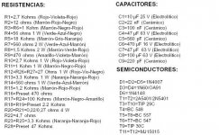
Traduction of part of the PDF
Beginning of functioning
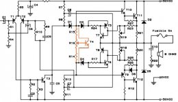
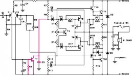
On the preamplifier, it have two low noise PNP transistors(like 2N5401) in class "A", in a configuration of differencial pair. The use of this transistors allows to use high feedback, like Continuous Current, or Alternate Current.
The output Differencial Pair is maked with T1 and t2, and it´s amplified with T3, and his components.
Next, the signal have a sufficient level as to be able to excite to the output transistors. Those transistors are polarized with a continuos tension (Vce of t4), and it is ajusted with R16. In synthesis: This tension is used to polarize the excited transistors(T9 and T10) and it delivery the quiet current of the output transistors.
The output Stage is in Symmetry cuasi-complementary, and is excited directly of T9 and T10; and are connected with the charge across R20 and R21.
The protection Circuit against Short circuits, is composed with transistors T5, T6, T7, T8, and the presets R18, R19 , which take a small portion of the drop tension, above the resistors R20 and R21, With what they detect when presents a short circuit to the output, and they annul the excitation(excitement) of the transitores excitadores.
In case of a complex load on the output make upper-tensions, They will be derived to the supply, across diodes D2 and D5. The Zobel are composed with C10 and R22, and it is used to make a "resistive load".
R28 is used To fix the level entry.
Beginning of functioning
On the preamplifier, it have two low noise PNP transistors(like 2N5401) in class "A", in a configuration of differencial pair. The use of this transistors allows to use high feedback, like Continuous Current, or Alternate Current.
The output Differencial Pair is maked with T1 and t2, and it´s amplified with T3, and his components.
Next, the signal have a sufficient level as to be able to excite to the output transistors. Those transistors are polarized with a continuos tension (Vce of t4), and it is ajusted with R16. In synthesis: This tension is used to polarize the excited transistors(T9 and T10) and it delivery the quiet current of the output transistors.
The output Stage is in Symmetry cuasi-complementary, and is excited directly of T9 and T10; and are connected with the charge across R20 and R21.
The protection Circuit against Short circuits, is composed with transistors T5, T6, T7, T8, and the presets R18, R19 , which take a small portion of the drop tension, above the resistors R20 and R21, With what they detect when presents a short circuit to the output, and they annul the excitation(excitement) of the transitores excitadores.
In case of a complex load on the output make upper-tensions, They will be derived to the supply, across diodes D2 and D5. The Zobel are composed with C10 and R22, and it is used to make a "resistive load".
R28 is used To fix the level entry.
Shakal said:teemuk, do you always find something wrong on other's amplifier projects? Is that a gift?
I think you have misunderstood me here: I don't think there's something "wrong" in this amplifier. In fact, similar circuit has been used in some pretty respected guitar/bass amplifiers from the 70's and I definitely wouldn't say that something is wrong with them either.
However, I'm curious about the alternative bootstrapping arrangement: It doesn't seem to be very popular and I'm curious why. Since this double bootstrapping method is not covered in most theory books either I'm just looking forward in hearing people's opinions about it in hope to learn something new.
By the way, I hope I'm not off-topic here as I seem to hold on to this detail...?
Hi Shakal,Shakal said:teemuk, do you always find something wrong on other's amplifier projects? Is that a gift?
I think its good though... spares others from making things thinking that is going to work well but it will not.
I have read Teemuk's original observations and his suggestion for further investigation.
I don't see this as picking holes in this project.
His reply clarifies what he originally said. "why is it less than popular"?
- Status
- Not open for further replies.
- Home
- Amplifiers
- Solid State
- Power amplifier 130w