The double bootstrap is interesting, and I have used it myself to see how it worked.
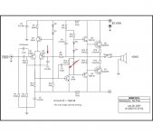
The 560R/1K5 top bootstrap passes 24mA, and the 1K/3K3 passes 11.3mA. The difference is passed to the voltage amplifier, which then has an easier job to do. The benefit is the much higher current which now drives the output stage, giving better slew rate for a low current voltage amp, which dissipates only around 600mW instead of 1.2W. In earlier times very fast, low Cob transistors of high dissipation were difficult to find and rather expensive.
By careful dimensioning of the bootstrap resistors it is possible to roll off the HF response a little earlier, helping with the Bode-Nyquist stability criteria.
An interesting design which should sound pretty good, but you never can tell unless you build it.......
Thanks for sharing,
Cheers,
Hugh
Thank you for the excellent description Hugh. Indeed, I can see this happening in a SPICE simulation now that I know what to look 🙂
This looks like a novel topology.
Considering the "glitches" and "ringing" I mentioned earlier; now that I investigated more, this seems to be a phenomenon related to rail sticking that (as far I understand) inherently troubles CCS loaded circuits: In conventional circuit with a single bootstrap (or active CCS) the positive half wave is more susceptible to sticking into rail during clipping while the negative half wave usually can clip without any prominent effect. When the PNP output transistor is equivalently fed by a CCS (as in double bootstrap topology) it will also begin to suffer from this phenomenon. The momentary sticking isn't as noticeable but will create a "glitch" or some ringing.
Well, those are my observations about the topic. My simulation circuits were quite crude and undoubtedly any good designs, where rail sticking effects are minimized anyway, are quite free from this trouble.
It seems very interesting.
Maybe some rail resistance can help...not only that one to the differential...but in other place..before the bootstrapp circuit.
Also trying the positive and negative rail resistances....better than PSSR or even the control against RF(HF)...much better is to separate the supplies..using two different voltage supplies, beeing bigger to the input side....if we cannot use double voltage supplies... using resistance into the rail and big condensers at the left side (low consumption side), you will have, as a consequence, less voltage fluctuations into the input...those voltage fluctuations can modulated the audio signal.... rail resistances, despite loose some volts into the output audio signal, will make the audio more clean...more stable amplifier will result.
I have found them extremelly usefull.
May your ringings and glitches will be reduced using them temuk... give a try..simulators do not burn fingers.... if did not result positive...you can just delete them.
The most normal is that designers makes those circuits to be extremelly stable...and they use to be filled with many condensers...all them can be reduce to tune the amplifier to sonics....yeah...they need to do that for safety reasons...and we need to tweak to our own pleasure when listening.
regards,
Carlos
R9-C9 results to more negative feedback at higher frequencies, thus limiting the HF gain and increasing stability (if implemented correctly). R2-C2 shunts high frequency signals from voltage amplifier transistor's base to rail, again in order to increase stability.
As an aside, the bootstrap both ways technique would be useful for complementary Mosfet output stages using transistors with high Vgs
I don´t have any information about boostrap... but, thanks to all for reply the thread.
¿What is the mean of: Bode-Nyquist stability criteria?
I don´t understand
¿What is the mean of: Bode-Nyquist stability criteria?
I don´t understand
aguantesoda said:I don´t have any information about boostrap... but, thanks to all for reply the thread.
¿What is the mean of: Bode-Nyquist stability criteria?
I don´t understand
Bootstrap (on supply) is enough easy to understand,
if the cap is a Vs/2 charged when the output line go at full positive
supply the driver reach Vsupply+Vs/2 of capacitor and vice-versa.
That means the supply of diver reach a tension greater than main supply.
Nyquist stability criteria is used for determining the stability of the system.
This is a math approach for verify that the system
work without oscillation..
http://en.wikipedia.org/wiki/Nyquist_stability_criterion
http://www.facstaff.bucknell.edu/mastascu/eControlHTML/Freq/Nyquist3.html
Push pull bootstrap ?Leolabs said:Very very interesting regarding the boostrap arrangement.
very useful also for T9 bjt saturation... 🙂
how can I Bridge this power amplifier? I need two identical stanges?
if i can... i will need a inversor circuit???
if i can... i will need a inversor circuit???
Yes, two amplifiers are needed and for most parts they should be as similar as possible. It's pretty easy to modify the configuration of the differential input stage so that it makes the other amplifier inverting, thus using additional phase inverter stage can be avoided. In theory the input is just connected to the non-inverting input instead (with a suitable series resistor) and that's it. In practice, the concerned 130W amp circuit should be modified more than this since input and feedback share the same resistor R4. The aforementioned trick will not work in this configuration. Also, there is no series resistor in the input that is essential for equalizing gains of inverting and non-inverting circuits.
I don't know if this circuit can be safely bridged but I would have to guess that no: The input stage as it is, in my opinion, is too simple to be replicated nearly identically in two circuits. Same thing with the bootstrap constant current sources loading the VAS. I think that these should be replaced with some sorts of active configurations that would ensure equal performance despite some component indifferences.
I don't know if this circuit can be safely bridged but I would have to guess that no: The input stage as it is, in my opinion, is too simple to be replicated nearly identically in two circuits. Same thing with the bootstrap constant current sources loading the VAS. I think that these should be replaced with some sorts of active configurations that would ensure equal performance despite some component indifferences.
Hi Aguantesoda,
you must be far from “plaquetodo” ´s circuits, these are old and in general without any test.
-----------------------------------------------------------------------------------
Mantenete lejos de los circuitos de "plaquetodo", son circuitos viejos y sin probar.
para que es el amp?
you must be far from “plaquetodo” ´s circuits, these are old and in general without any test.
-----------------------------------------------------------------------------------
Mantenete lejos de los circuitos de "plaquetodo", son circuitos viejos y sin probar.
para que es el amp?
Hi daol, I want to use it to amplify sounds in general. The problem is that I need at least 130w, because the end(purpose) is to use it for my band of music.
Thanks
in Spanish:
Hola que tal daol quería usarlo para amplificar sonidos en general. El problema es que necesito al menos 130w, porque el fin es utilizarlo para mi banda de música.
¿Vos ya lo probaste este amplificador?
Gracias,
Guido
Thanks
in Spanish:
Hola que tal daol quería usarlo para amplificar sonidos en general. El problema es que necesito al menos 130w, porque el fin es utilizarlo para mi banda de música.
¿Vos ya lo probaste este amplificador?
Gracias,
Guido
Hello,
you need at least two or three pairs of output transistors for your application (heavy duty amp).
I will look for any circuit and I will send it.
Regards.
----------------------------------------------------------------------------------
Hola,
necesitas dos o tres pares de transistores de salida (un amp resistente).
Voy a buscar algun circuito y te lo envío.
Saludos.
aguantesoda said:Hello, I found this power amplifier in a book; and I want to know a little about it, before make it.
What is R7 - R8 - C8 doing?
What is R13 - R11 - C7 doing?
PD: I write in spanish too, because I dont speak very well in english. Thanks!
In Spanish:
Hola, encontré este amplificador en una revista, y voy a armarlo, pero antes de eso me gustaría aprender un poco acerca de él.
¿Que función cumple R7 - R8 - C8?
¿Que función cumple R13 - R11 - C7?
PD: Perdón por escribir en los dos idiomas, pero no hablo mucho inglés, y por temor a equivocarme y por las dudas lo agrego. Gracias!
😀
Hiii aguantesoda ...
Your schem looks same whit me.....????
Attachments

Re: Re: Power amplifier 130w

Sorry I mean like this one ????
Thak's
big HUggge....
Bee C. said:
😀
Hiii aguantesoda ...
Your schem looks same whit me.....????
Sorry I mean like this one ????
Thak's
big HUggge....
Attachments
Sure...
Yup...I think u right...

daol said:Hi, with +/- 42 volts you have 100 watts/8 ohms, no more.
Yup...I think u right...
Re: Sure...
They are similar, yes.
How it Sounds?
On +/- 42V, 8 ohms you will obtain ~110w
Bee C. said:
Yup...I think u right...
They are similar, yes.
How it Sounds?
On +/- 42V, 8 ohms you will obtain ~110w
Hi,On +/- 42V, 8 ohms you will obtain ~110w
no it won't.
It won't even do 100W into 8r.
I'd guess it might manage 80W into 8r just before clipping.
- Status
- Not open for further replies.
- Home
- Amplifiers
- Solid State
- Power amplifier 130w