qsa said:@ khalsa check your account
Or his typing 😉 My guess is that khalsaaudiocenter@yahoo.com will work.
Hi have sent to all today
who email me NMOS Power Board (with DC detect and Turn on Delay) and NMOS Amplifier X Gerber Files with Schematics and PCBs Layout
Questions or improvements are welcome
I think about forthcoming to add CLASS H with SMPS Power Board for NMOS Amp....
Does somebody know low cost PCB Supplier in Europe or in the world for small order,
in Germany local PCB Suppliers charge us with 200 EUR equal. to 260 USD for 2 green plastic Board sample PCB ?
qsa pcb
hi qsa
greetings will tell you price of pcb as pcb factory is next to my house
thanking you
andrew lebon
hi qsa
greetings will tell you price of pcb as pcb factory is next to my house
thanking you
andrew lebon
am watching this thread with GREAT interest...also would like to but a couple of PCB's...pls send details to floydsec@gmail.com
Hi everyone
I am building one more Nmos500 with original Quasi board. I just want to ask one thing on the amp board can I use 470UF 100V caps instead of 470UF 200?
I am going to run it with +/- 67VDC rail. With +/-67VDC what power should I get from Nmos 500 in 8ohm?
Thanks
Regards
I am building one more Nmos500 with original Quasi board. I just want to ask one thing on the amp board can I use 470UF 100V caps instead of 470UF 200?
I am going to run it with +/- 67VDC rail. With +/-67VDC what power should I get from Nmos 500 in 8ohm?
Thanks
Regards
You can also check some old posts like
http://www.diyaudio.com/forums/showthread.php?threadid=131439&highlight=
http://www.diyaudio.com/forums/showthread.php?threadid=125821
http://www.wincircuits.com.tw/
I saw another one on the Stereophile web page a year or two ago but I guess it isn't advertising there any more. It was really low price and for me shipping charges were too high. Might be cheaper to your place. I'll look for it.
Hello Quasi
long time nothings hear, do you have final design for Nmos 350Mk II now ?
cant find MK II schematic on your website since today, or was is it only prototype for test ?
long time nothings hear, do you have final design for Nmos 350Mk II now ?
cant find MK II schematic on your website since today, or was is it only prototype for test ?
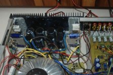
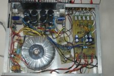
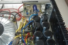
At Last!
Finally completed my amp based on the NMOS 350. Been testing it, the dynamic range is awesome😀 Trying to post some pics.
Hari
Finally completed my amp based on the NMOS 350. Been testing it, the dynamic range is awesome😀 Trying to post some pics.
Hari
Re: At Last!
tell us what the dynamic range that you measured was.jethari said:Been testing it, the dynamic range is awesome
Re: Re: At Last!
Andrew
Unfortunately, I dont use instruments for testing amps, only my ears, been playing various types of music including my vinyls and in my experience they never sounded this good.
Hari
AndrewT said:tell us what the dynamic range that you measured was.
Andrew
Unfortunately, I dont use instruments for testing amps, only my ears, been playing various types of music including my vinyls and in my experience they never sounded this good.
Hari
strange DC output
Hi all,
I've been using this amp (Nmos 500) for a while. At the start I had trouble with fake fet's, which caused a big bang (there are pictures of it somewhere on here).
Anyway, since then i have re-done the amp and have been running it nicely for over a year. I decided to turn the amp into an instrument amp, and installed a valve preamp before the amp. However this caused the amp to have a very strange 1.5V dc on the output. Sometimes the DC voltage gets up to 2.5V and trips off the DC protection relay.
So I spent ages trying to find out why the preamp would put 1.5V dc on the output. The output of the preamp is 0.09 Vdc, so its not from that. I am stumped. When I disconnect the preamp from the amp inputs the 1.5V dc goes away.
Also, after about 10 min of testing at very very low volumes (hardly audible, and with the preamp plugged in) the heat sink got really warm (not hot). Soon after i found that out one of the 27R resistors smoked, and i turned the amp off as quick as i could.
Any ideas?? im at a loss, been trying to work it out all day... 🙁
Cheers.
Most probably the amp is oscillating as soon as you connect the preamp.
Perhaps you have to increase the Vas miller capacitor, if you have one. Try that first, increase the value until you reach about 100 pf.
If you do not have results increase the driver compenstation capacitors.
Maybe it helps!
Perhaps you have to increase the Vas miller capacitor, if you have one. Try that first, increase the value until you reach about 100 pf.
If you do not have results increase the driver compenstation capacitors.
Maybe it helps!
Hi,
I can't recall the input of the Nmos500.
Does it have a low pass filter and a high pass filter on the input?
Does it have a DC blocking capacitor on the NFB loop (another input)?
I can't recall the input of the Nmos500.
Does it have a low pass filter and a high pass filter on the input?
Does it have a DC blocking capacitor on the NFB loop (another input)?
Also the preamp has 90mv output. It is pleanty. If you multiply that to 33 (gain) you have 2,7 volts
thanks for the quick reply.
The Nmos500 does have input filters (hi and low pass). This should also explain why there should not be any DC input into the diff amp stage. If there were no input filters then 33 gain would explain the 2.7 volts.
also NFB loop? i'm not familiar with that term
VAS miller capacitor is 39pF. i might try increasing that and see if that helps.
Also i should say i have tried changing VR1 (output offset voltage) but it doesn't make any difference to the output at all.
if I have found the correct schematic then
C1 =DC blocking capacitor and with R3 forms the high pass input filter
C2 = RF and with R1 forms the low pass filter
C7 = DC blocking capacitor in the NFB loop.
Are all three fitted?
What are the values?
is C8, 10pF fitted?
C1 =DC blocking capacitor and with R3 forms the high pass input filter
C2 = RF and with R1 forms the low pass filter
C7 = DC blocking capacitor in the NFB loop.
Are all three fitted?
What are the values?
is C8, 10pF fitted?
yes all those capacitors are fitted, and their values are the same as those on the schematic (you seem to have found the same one I am using).
C1 is a 1uF greencap, C2 is a 330pF ceramic, C7 is a 100uF 63v electrolytic, and C8 is installed, and it was marked as a 10pF ceramic.
I was thinking, it could have been the amp oscillating. When i hooked the output of the amp up to the cro i could see there was something, but it was too HF to see on my cro in detail. could it be the output impedance of the preamp is making the amp oscillate?
I plan to get some new capacitors today, im going to change C4 up to something higher and see if that helps.
thanks 🙂
- Home
- Amplifiers
- Solid State
- Power amp under development