Whar is yours assessment about this audio amplifier (see image)?
A compact design audio amplifier with: LED indicators show output voltage and headroom; clip limiter; DC, overload and temp protections, balanced inputs, soft start output, audio preamplifiers and variable speed fan with temperature heat sink.
Technical Specifications:
Power in to 4 Ohm load: 400W;
THD = 0,02%;
Power supply: +/-70Vcc
This amplifier is designed by me and costs around 50Euro without VAT.
Attachments

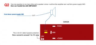
Hi anyone can help!!
Can I use Switch Mode power supply with this amplifier?
Look this SMPS? http://www.redrocksaudio.es/e_main.html
Wasim
Can I use Switch Mode power supply with this amplifier?
Look this SMPS? http://www.redrocksaudio.es/e_main.html
Wasim
Hi,
you could try, but who can guarantee the result?
First question:-
what is the peak transient current that the amplifier will demand from the SMPS when driving a real speaker?
Where does that current come from?
What size of SMPS will be needed to meet that demand?
you could try, but who can guarantee the result?
First question:-
what is the peak transient current that the amplifier will demand from the SMPS when driving a real speaker?
Where does that current come from?
What size of SMPS will be needed to meet that demand?
That kind of SMPS topology is perfect for delivering high peak currents without problems without having to design for continous high power. It's the same as QSC uses (but with an added PFC) and I believe Crown also have used the same topology.
There is no output inductor to saturate so output current is only limited by transformer, diode and transistor dissipation. If IGBT:s are used high peak currents are no problem at all.
Thanks to the high output peak current capability most energy storage can be moved to the primary side - which is good because for the same energy storage electrolytics are smaller at high voltage.
add gate resistors to the six FETs.
bypass the 2uH with ~4r0
The 18k in the LTP tail is dropping between 60 & 70 Volts.
Try halving this value, maybe 10k.
bypass the 2uH with ~4r0
The 18k in the LTP tail is dropping between 60 & 70 Volts.
Try halving this value, maybe 10k.
zerohead_ak47 said:its good working
Good news that you have built a working Nmos mkII. Do you have a PCB layout for this? Anyway how does it sound?
AndrewT said:add gate resistors to the six FETs.
bypass the 2uH with ~4r0. The 18k in the LTP tail is dropping between 60 & 70 Volts. Try halving this value, maybe 10k.
Andrew's advice is sound, you should add gate resistors to each FET gate. This will help protect against oscillations.
Assuming 0.6v drop for the diode and transistor junctions the current through the 18k resistor will be 3.33mA equating to a voltage drop of 60v, leaving 10v across the ccs transistor. The resistor could be reduced to 15k leaving 20v across the transistor if desired.
megajocke said:And source resistors for the FETs in the negative rail
These resistors should be moved as Megajocke suggests. This will improve the current sharing between the negative rail FETs.
Other thoughts are:
- Put a 0.1uf capacitor across the zener.
- Increase the filter capacitors on FET rails to 1,000uF.
- The 100uF capacitor on the rails feeding the 1st & 2nd stage could cause problems if not grounded correctly. In practice it is not needed so if you have any noise issues try removing it.
Cheers
Quasi
Hi,
Starting to do the series with the nmos 200 first. How similiar is irfp240 to irfp260 for this application (TO-247 version)?
Tks
Starting to do the series with the nmos 200 first. How similiar is irfp240 to irfp260 for this application (TO-247 version)?
Tks
Thanks weissi
Do I need to change the power resistors in to 0.27ohm5w or should remain the same?
Wa
Do I need to change the power resistors in to 0.27ohm5w or should remain the same?
Wa
Wasim said:Thanks weissi
Do I need to change the power resistors in to 0.27ohm5w or should remain the same?
Wa
You can use the same values for the power resistors. It should work just as well.
Hari
hi quasi
matching pre amplifier for nmos350 please
iam playing the amp directly from computer sound card
matching pre amplifier for nmos350 please
iam playing the amp directly from computer sound card
- Home
- Amplifiers
- Solid State
- Power amp under development