Hi John
Yes, now I've got the idea. Working on it right now but not for long - its already 2300Hrs here 😱 I'll post the updated layout soon as it is finished.
Hari
Yes, now I've got the idea. Working on it right now but not for long - its already 2300Hrs here 😱 I'll post the updated layout soon as it is finished.
Hari
Some Important Typo Error Corrections to My Post #1997
Re Post #1997 Some important typo corrections below I missed seeing after I could not edit the message anymore:
Correction below as I got my BCE, CBE, EBC's missed up while converting 8 ohm power to 4 ohm power:
The second point regarding 90dB drivers is with no passive crossover the effective sensitivity of the driver is 90dB. Just so you have a context, with a 16W RMS amplifier for 8 Ohms the 90dB 4 Ohms driver can put out 102dB RMS and 105 dB peak assuming a perfect PSU and amplifier. At 300W RMS for 8 Ohms, you would have a bit over 117dB RMS and 120dB peak, again assuming a perfect PSU and amplifier.[snip]
Correction to clarify reference to (omitted) pairs of IRFP450s or equivalent:
The 25-0-25 12A transformer you have would be excellent for the four channels, the L and R for front and rear, with about 60W RMS for 8 ohms. If you already have the 44-0-44 500VA toroid I would use that for subwoofer with the 4 ohm drivers in series and run the centre channel off the other side using at least 3 pairs of IRFP450s or equivalent power handing MOSFETs.
[snip]I have stress tested the amp with a sine wave inputs in the 20Hz to 100Hz range and it cuts out thermally at tad above half volume. Once the heatsinks cool down a bit the relay based protection resets. At about 3-6 dB less (than just above midpoint) the same amp holds its own with the same sine wave test signal, though the heatsinks run very warm. At normal listening levels which the volume is again about half point the heatsinks run cool.[snip]
Regards,
John L. Males
Willowdale, Ontario
Canada
14 July 2007 (13:10 -) 13:56
14 July 2007 13:59 Typo correction. Gosh Correcting the correction. lol jlm
Official Quasi Thread Researcher
Re Post #1997 Some important typo corrections below I missed seeing after I could not edit the message anymore:
keypunch said:
[snip]
The second point regarding 90dB drivers is with no passive crossover the effective sensitivity of the driver is 90dB. Just so you have a context, with a 16W RMS amplifier for 8 Ohms the 90dB 4 Ohms driver can put out 108dB RMS and 111 dB peak assuming a perfect PSU and amplifier. At 300W RMS for 8 Ohms, you would have a bit over 120dB RMS and 123dB peak, again assuming a perfect PSU and ampliier.[snip]
Correction below as I got my BCE, CBE, EBC's missed up while converting 8 ohm power to 4 ohm power:
The second point regarding 90dB drivers is with no passive crossover the effective sensitivity of the driver is 90dB. Just so you have a context, with a 16W RMS amplifier for 8 Ohms the 90dB 4 Ohms driver can put out 102dB RMS and 105 dB peak assuming a perfect PSU and amplifier. At 300W RMS for 8 Ohms, you would have a bit over 117dB RMS and 120dB peak, again assuming a perfect PSU and amplifier.[snip]
The 25-0-25 12A transformer you have would be excellent for the four channels, the L and R for front and rear, with about 60W RMS for 8 ohms. If you already have the 44-0-44 500VA toroid I would use that for subwoofer with the 4 ohm drivers in series and run the centre channel off the other side using at least 3 IRFP450s or equivalent power handing MOSFETs.
Correction to clarify reference to (omitted) pairs of IRFP450s or equivalent:
The 25-0-25 12A transformer you have would be excellent for the four channels, the L and R for front and rear, with about 60W RMS for 8 ohms. If you already have the 44-0-44 500VA toroid I would use that for subwoofer with the 4 ohm drivers in series and run the centre channel off the other side using at least 3 pairs of IRFP450s or equivalent power handing MOSFETs.
[snip]
[snip]I have stress tested the amp with a sine wave inputs in the 20Hz to 100Hz range and it cuts out thermally at tad above half volume and once the heatsinks cool down a bit the relay based protection resets. At about 3-6 dB the same amp holds its own with the same sine wave test signal, though the heatsinks run very warm. At normal listening levels which the volume is again about half point the heatsinks run cool.[snip]
[snip]I have stress tested the amp with a sine wave inputs in the 20Hz to 100Hz range and it cuts out thermally at tad above half volume. Once the heatsinks cool down a bit the relay based protection resets. At about 3-6 dB less (than just above midpoint) the same amp holds its own with the same sine wave test signal, though the heatsinks run very warm. At normal listening levels which the volume is again about half point the heatsinks run cool.[snip]
I hope this information is helpful Vivek.
Regards,
John L. Males
willowdale, Ontario
Canada
14 July 2007 (09:15 -) 11:10/11:17
14 July 2007 11:36 Typo correction. jlm
14 July 2007 11:41 Typo corrections. jlm
14 July 2007 11:43 Typo corrections. jlm
Official Quasi Thread Researcher
Regards,
John L. Males
Willowdale, Ontario
Canada
14 July 2007 (13:10 -) 13:56
14 July 2007 13:59 Typo correction. Gosh Correcting the correction. lol jlm
Official Quasi Thread Researcher
Hi John,
Thanks a million for that explanation. It is just brilliant. So why don't I build one Nmos350 (or even the 500), wire the two subs in series and see how it works out. If I feel it suits my requirement, then no problems at all. If not, I could build one more 350W amp to power the other sub.
As regards the other five channels, the Denon (AVR 1403) receiver I have will put out 65W per channel. I only needed to build one sub and an amp for it.
I will invest in a good transformer -- sufficient for two amp modules -- just in case I decide to build the second one.
Regarding the mosfet vs bjt discussion, I have felt that the bipolars have a warmer sound than the mosfets. So, I thought I would try it out. However, if the mosfets can comparatively be pushed harder, I don't mind at all. After all, I may tend to push the subwoofer while watching movies.
Thanks again,
Vivek
Hi Vivek,
Your idea of building one amplifier first, either NMOS350 or NMOS500, with the 4 ohm woofers in series first makes sense, but you will need to buy a transformer based on 4 ohm VA capability should you decide to you need to build a second amp and power each with its own amplifier. Point here is if you are happy with the series connected 4 ohm drivers then you will likely be fine with the 44-0-44 500VA toriod. If not you will need two transformers of at least 700VA, one for each 4 ohm driver in the two amplifier configuration. I say at least because if you decide to go to the NMOS500 you will be at a higher rail voltage, plus the added current demands so you will need to calculate the required VA at the higher NMOS500 operating rail voltage. It will also cost more as you will need additional capacitance for the PSU rails. For less than a 3 dB gain I do not think it will be worth the extra cost of the transformer and capacitors. As I mentioned this not quite 3dB and just dynamic headroom which I doubt very much you will be able to notice, let alone use all that often.
What might be a better approach is to use two parallel and larger value rail filter capacitors on the PCB as well as some extra capacitance in the PSU. I think that is more likely to make a difference you may hear more using a higher power amplifier, VA related transformer costs, and additional capacitance for higher rail voltage. This will give you more reserve which will allow for better dynamics. There is also some who believe in a slightly different PSU design that goes more to improving sound and dynamic power response than increasing the amplifier power. There are some who have done so and discussed in this thread.
Regarding the BJT sound, I think for a subwoofer there will not be as much of a difference in the "sound" of BJT or MOSFET. This of course depends on the crossover frequency and order of crossover to some extent.
Regards,
John L. Males
Willowdale, Ontario
Canada
14 July 2007 (14:24 -) 14:49
14 July 2007 14:51 Typo correction. jlm
Official Quasi Thread Researcher
Opps Typo Error, Missing Word Changes Meaning My Post #2004
Vivek,
Sorry I made a serious typo error in Post #2004 I just happened to noticed to second paragraph, second sentance. I missed a "than" which I have bolded in the corrected sentance below:
"I think that is more likely to make a difference you may hear more than using a higher power amplifier, VA related transformer costs, and additional capacitance for higher rail voltage."
My appologies again.
Regards,
John L. Males
Willowdale, Ontario
Canada
14 July 2007 18:26
Official Quasi Thread Researcher
keypunch said:Hi Vivek,
Your idea of building one amplifier first, either NMOS350 or NMOS500, with the 4 ohm woofers in series first makes sense, but you will need to buy a transformer based on 4 ohm VA capability should you decide to you need to build a second amp and power each with its own amplifier. Point here is if you are happy with the series connected 4 ohm drivers then you will likely be fine with the 44-0-44 500VA toriod. If not you will need two transformers of at least 700VA, one for each 4 ohm driver in the two amplifier configuration. I say at least because if you decide to go to the NMOS500 you will be at a higher rail voltage, plus the added current demands so you will need to calculate the required VA at the higher NMOS500 operating rail voltage. It will also cost more as you will need additional capacitance for the PSU rails. For less than a 3 dB gain I do not think it will be worth the extra cost of the transformer and capacitors. As I mentioned this not quite 3dB and just dynamic headroom which I doubt very much you will be able to notice, let alone use all that often.
What might be a better approach is to use two parallel and larger value rail filter capacitors on the PCB as well as some extra capacitance in the PSU. I think that is more likely to make a difference you may hear more using a higher power amplifier, VA related transformer costs, and additional capacitance for higher rail voltage. This will give you more reserve which will allow for better dynamics. There is also some who believe in a slightly different PSU design that goes more to improving sound and dynamic power response than increasing the amplifier power. There are some who have done so and discussed in this thread.
Regarding the BJT sound, I think for a subwoofer there will not be as much of a difference in the "sound" of BJT or MOSFET. This of course depends on the crossover frequency and order of crossover to some extent.
Regards,
John L. Males
Willowdale, Ontario
Canada
14 July 2007 (14:24 -) 14:49
14 July 2007 14:51 Typo correction. jlm
Official Quasi Thread Researcher
Vivek,
Sorry I made a serious typo error in Post #2004 I just happened to noticed to second paragraph, second sentance. I missed a "than" which I have bolded in the corrected sentance below:
"I think that is more likely to make a difference you may hear more than using a higher power amplifier, VA related transformer costs, and additional capacitance for higher rail voltage."
My appologies again.
Regards,
John L. Males
Willowdale, Ontario
Canada
14 July 2007 18:26
Official Quasi Thread Researcher
Man that was a lot to read;
By the time I got to the end I forgot what I read at the start.
Anyway my view of the situation is.
Using 44v 0v 44v 800va transformer and one Nmos500 approximate powers for for 8 ohms vs 2 ohms is 160 watts vs 515 watts. This is too big a difference for the 8 ohm option to be considered.
Using 44v 0v 44v 800va transformer and two Nmos350 approximate power for for 4 ohms is about 270 watts x 2 allowing for supply sag.
So costs aside, the best option is 2 x Nmos350's because you get the added benefit of better power spread with 12 FETs effectively handling the load instead of a maximum of 10. Plus you'll have more area to spread the heat.
But this will cost more...so up to you.
Your 25v 0v 25v transformer will give you just under 50 watts per channel into 8 ohms, around 90 into 4 ohms and maybe 160 into 2 ohms.
Finally, that was a pretty impressive amount of text John. I'm sure that when we conduct your annual performance review as OQTR you will receive a substantial percentage increase in remuneration.
Cheers
Q
BJT v Nmos
I agree that using the BJT version "Brother of Quasi" would be wasted on a subwoofer application. In terms of sound quality it should slightly surpass the Nmos amps.
Cheers
Q
I agree that using the BJT version "Brother of Quasi" would be wasted on a subwoofer application. In terms of sound quality it should slightly surpass the Nmos amps.
Cheers
Q
Re: Man that was a lot to read;
Does this mean a stock option plan? Perhaps a quasi store stock option plan?
"Researching" for that new condo in Adelaide, Australia as second home,
John L. Males
Willowdale, Ontario
Canada
14 July 2007 22:18
Official Quasi Thread Researcher
quasi said:[snip]
Finally, that was a pretty impressive amount of text John. I'm sure that when we conduct your annual performance review as OQTR you will receive a substantial percentage increase in remuneration.
Cheers
Q
Does this mean a stock option plan? Perhaps a quasi store stock option plan?
"Researching" for that new condo in Adelaide, Australia as second home,
John L. Males
Willowdale, Ontario
Canada
14 July 2007 22:18
Official Quasi Thread Researcher
Hi Quasi & everybody, long time no see 😀
I just want to ask that is there anybody here have prob with the layout files on Quasi's homepage? I downloaded all those files, but I couldn't open them with my Sprint layout.
Quasi, can you check them for me, thanks alot!
I just want to ask that is there anybody here have prob with the layout files on Quasi's homepage? I downloaded all those files, but I couldn't open them with my Sprint layout.
Quasi, can you check them for me, thanks alot!
hoangduongo said:Hi Quasi & everybody, long time no see 😀
I just want to ask that is there anybody here have prob with the layout files on Quasi's homepage? I downloaded all those files, but I couldn't open them with my Sprint layout.
Quasi, can you check them for me, thanks alot!
Yes it's been a while Hoangduongo. Good to see you haven't changed a bit.
For some strange reason the files need to be saved to the hard disk first before they can be opened. I'll see if there is something that can be done to change this. In the meantime right click the link and select "save as".
Cheers
Q
quasi said:
For some strange reason the files need to be saved to the hard disk first before they can be opened. I'll see if there is something that can be done to change this. In the meantime right click the link and select "save as".
Cheers
Q
Yes, Quasi, I've downloaded each file twice to my hard disk, but I still couldn't open them, my Sprint layout kept saying that those file are not Sprint-layout files 😕
Rgds
Hi,jethari said:Here is the updated pcb layout with all the suggested corrections. Tell me what you think of it.
almost every cap has space to one or both ends.
Use the space to add in alternative pin pitch options for every cap.
small electros, small PP film and PES film 0.2inch & 0.3inch
larger PP film 0.4inch, 0.6inch, 0.9inch.
Try to ensure that C1 can accomodate 2u2F and maybe even as big as 4u7F.
hoangduongo said:
Yes, Quasi, I've downloaded each file twice to my hard disk, but I still couldn't open them, my Sprint layout kept saying that those file are not Sprint-layout files 😕
Rgds
I don't know what the problem could be. What version sprint are you using? I'm using version 5.0 with the latest update.
Can you email the file you downloaded to me? quasiweb@adam.com.au
Cheers
Quasi
quasi said:
I don't know what the problem could be. What version sprint are you using? I'm using version 5.0 with the latest update.
Can you email the file you downloaded to me? quasiweb@adam.com.au
Cheers
Quasi
That's the prob, Quasi, I'm using ver 4.0.
Don't tell me to upgrade to ver 5.0 'cause I can't afford it 😀
It's the best that you can save your designs in ver 4.0 and upload for 4.0 users.
Rgrds.
P.S: Now I have to go right now (I'm going on my vacation) or my mom will kill me (I'm serious) so I can't send you the files. See you next week then I'll send you the files.
hoangduongo said:
That's the prob, Quasi, I'm using ver 4.0.
Don't tell me to upgrade to ver 5.0 'cause I can't afford it 😀
It's the best that you can save your designs in ver 4.0 and upload for 4.0 users.
Rgrds.
P.S: Now I have to go right now (I'm going on my vacation) or my mom will kill me (I'm serious) so I can't send you the files. See you next week then I'll send you the files.
No problem, I hope you survive. Lets make contact again next week. Enjoy your vacation.
Cheers
Q
jethari said:Hi Quasi, Key and everybody else,
Here is the updated pcb layout with all the suggested corrections. Tell me what you think of it.
Thanks
Hari
Hi Hari,
Nice board. I like the way you have arranged T1 & T5 allowing for some thermal coupling. It looks like you are going to use 2SC1845's here?
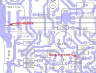
Can I make a couple of suggestions.
1. You should use a seperate track from the fuse for the FET rail bypass capacitors. This will keep the capacitor charge / discharge currents seperate from the track feeding the FETs.
2. As much as possible you should retain the star grounding arrangement after the 10 ohm resistor. The reason is to keep all the components using this ground at exactly the same potential. You would be surprised how much difference 1cm of track junction can make.
I have attached a snap of my layout to show what I mean.
Cheers
Q
Attachments
Quasiquasi said:
Hi Hari,
Nice board. I like the way you have arranged T1 & T5 allowing for some thermal coupling. It looks like you are going to use 2SC1845's here?
Can I make a couple of suggestions.
1. You should use a seperate track from the fuse for the FET rail bypass capacitors. This will keep the capacitor charge / discharge currents seperate from the track feeding the FETs.
2. As much as possible you should retain the star grounding arrangement after the 10 ohm resistor. The reason is to keep all the components using this ground at exactly the same potential. You would be surprised how much difference 1cm of track junction can make.
I have attached a snap of my layout to show what I mean.
Cheers
Q
Thanks for the compliment. I will be using 2sc2240 for T1 and T5. BTW the thermal coupling arrangement is courtesy Andrew.
1. I'm amending the tracks to the filter caps, there is enough space as it is.
2. I've managed to provide the star ground. But the line going to C2/R3 cannot be helped.
I'll post the amended layout later.
Hari
Hi Hari,
The board is looking progressing great.
Any reason some tracks have a dark line around them? It is a bit distracting is all.
The wire link beween R35/R17 may need to be made wider and if possible bolded so it is not mistaken as a track and some might think the link should connect to T7. If you take a look at quasi's visual effect to show the wire link in the NMOS350/500 you see the visual manner the wire link stands out while also so labled with text as you have added pointing to the wire link. Also make sure when you create the tracks only image this wirelink does not appear on the tracks image. The wirelink should only show in the "layout" version of the PCB image as does with the NMOS350/500.
Regards,
John L. Males
Willowdale, Ontario
Canada
15 July 2007 (11:10 -) 12:11
Official Quasi Thread Researcher
P.S. quasi, I was not able to use the URL for the NMSO350/500 to your Web Site with the diyAudio HTML coding. The single quote in the "pdf's" part of the URL is causing all sorts of problems and I have not been able to find an alternate URL coding to work. jlm
- Home
- Amplifiers
- Solid State
- Power amp under development