Riche Lemuey said:Hi,
interesting design... i wanna try...
but... theres something bothering me... the cost...
man, FET transistors were too expensive here in our country...
how about, instead of using FET's,,, i use common output transistors... how shall i incorporate it?
thanx...
regards,
Riche🙂
Riche,
There is a similar design known as the Brother of Quasi you will likely find meets your needs. On quasi's web site pages the link for the desigh is known as "N-Bip300" with the latest schematics and PCBs.
Regards,
John L. Males
Willowdale, Ontario
Canada
01 July 2007 14:24
Official Quasi Thread Researcher
Re: MOSFET Rating
cd-i,
Thanks for your reply regarding my MOSFET question of Vdss should be Vrail or Vrail*2.
Regards,
John L. Males
Willowdale, Ontario
Canada
01 July 2007 14:42
Official Quasi Thread Researcher
cd-i,
Thanks for your reply regarding my MOSFET question of Vdss should be Vrail or Vrail*2.
Regards,
John L. Males
Willowdale, Ontario
Canada
01 July 2007 14:42
Official Quasi Thread Researcher

And one more
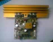
most parts of the amp were rescue from older projects except for the resistors and capacitors.
I had a hard time with the heatsink of T7 couse of the size of the resistors.
BTW, maybe my heatsink is to small but the amp gets really hot i would say 50ºC or 55ºC or above, is that normal?, or safe?,
remember im using a +/-33 power supply
Sorry my poor english
Attachments
Juan Spektor said:
I had a hard time with the heatsink of T7 couse of the size of the resistors.
BTW, maybe my heatsink is to small but the amp gets really hot i would say 50ºC or 55ºC or above, is that normal?, or safe?,
remember im using a +/-33 power supply
Sorry my poor english
Juan,
What output devices are you using?
The heatsink temperature is 50-55C at idle or when you play music? For sure at idle that is far too high. I would be inclined to suggest that perhaps the heatsink is either too small or your module has a oscillation problem. The latter would cause the module to behave like it had a constant signal which would drive the amplifier temperature up.
If the problem is a module oscillation problem, I cannot recall off hand how you first confirm it without the use of an oscilloscope. There are simple techniques to do so.
http://sound.westhost.com/troubleshooting.htm#comm3 will give you a sense of the possible causes of oscillation.
I searched the internet and diyAudio for audio amp oscillating and as usual no luck finding what I know I have seen in past when not looking. There is one technique of using a conventional household light blub to confirm the oscillation. If I was to trust my memory (remember my age goes back to tube days) a household light blud was put in series with the one side of the ac line to the transformer. If the blub glows steady, as opposed to an initial glow that disappears after a few seconds, then you have an oscillation problem which woudl likely be the cause of the heatsinks being 50-55C.
Are you certain that T7 is thermally attached to the heatsink?
Of course there could be some error in a the BCE, CBE, EBC, et al oritentation of your T7 or some other transistor, solder bridge on the PCB, a defective part, et al.
I am sure the thread "experts" can follow up with you on what I have suggested and more than likely missed or do not have the knowledge to give you further assistance.
Regards,
John L. Males
Willowdale, Ontario
Canada
01 July 2007 23:00
Official Quasi Thread Researcher
Hi Juan
If the quiescent current of the amp output stage is set to 30mA per FET pair then the output stage will dissipate about 4 watts. Add to that the driver stage dissipating about 1 watt. This continous dissipation will warm the heatsink up.
The only way to be sure about the situation is to take some measurements. With the amp idling (nothing connected except power) measure the voltage across across one of the 1 ohm source resistors. You should get 15mV with an idle current of 30mA. Check to see that it's the about the same for all the 1 ohm pairs.
If the voltages are very different then you could have a problem.
Does your amp play music clearly? If it does and you get the measurements above then the amp module is ok.
One more thing you should heatsink both T6 & T7.
Cheers
Q
Re: Web Update
Hi Quasi,
I used the E96 resistor values as 1% resistors are common and often many DIY Audio people will use 1% for less thermal noise.
I like the idea of different R17 values based on different rail voltages. I had been making such calculations myself for my own purposes.
Correct me if I am wrong, but builders should not mix different gains for the same source, often the case in HT configurations, but Bi-Amp or Tri-Amp would also be a similar configuration of concern. For example one might use the 64W (+-40VDC rails) for HT Centre, Front and Rear, and 185W (+-65VDC rails) for the subwoofer. This would be result in amplifier gains of 22 and 33 which would cause system channel mismatching with the subwoofer. If this was applied to Bi-Amping instead for 64W mid/high and 185 low then the gain difference would be more pronounced. What this means is builders need to be aware of the gain they choose and use the same gain for all power versions of the amps being used for a given system. The suggestions I would have are either use the lowest gain for all amps or pick a gain in the middle of the range.
I am not sure how important it is, but it was my understanding R17 and R3 should be the same value for the lowest DC offset. If this is true, then C1 will need adjusting to ensure R3 is about the 4.8229 Hz input filter rolloff. I am not sure if C2 will also need recalculation as it is my understanding C2 is related to R1 for cut off frequency.
Regards,
John L. Males
Willowdale, Ontario
Canada
02 July 2007 08:24
Official Quasi Thread Researcher
quasi said:Hi folks,
Updated the web site a bit tonight.
In the power selection table, I have downgraded acheivable powers a little to better reflect a real world practical build. I have also taken advice from John (OQTR) and AndrewT and have inserted suggested fuse ratings. I have also applied some values for R6 & R17.
Note; my approach is a bit different. I have tried to return to more common values for resistors (E12) and fuses.
Cheers
Q
PS. Sebastian, you are welcome to transfer any information you like to your (better) web site.
Hi Quasi,
I used the E96 resistor values as 1% resistors are common and often many DIY Audio people will use 1% for less thermal noise.
I like the idea of different R17 values based on different rail voltages. I had been making such calculations myself for my own purposes.
Correct me if I am wrong, but builders should not mix different gains for the same source, often the case in HT configurations, but Bi-Amp or Tri-Amp would also be a similar configuration of concern. For example one might use the 64W (+-40VDC rails) for HT Centre, Front and Rear, and 185W (+-65VDC rails) for the subwoofer. This would be result in amplifier gains of 22 and 33 which would cause system channel mismatching with the subwoofer. If this was applied to Bi-Amping instead for 64W mid/high and 185 low then the gain difference would be more pronounced. What this means is builders need to be aware of the gain they choose and use the same gain for all power versions of the amps being used for a given system. The suggestions I would have are either use the lowest gain for all amps or pick a gain in the middle of the range.
I am not sure how important it is, but it was my understanding R17 and R3 should be the same value for the lowest DC offset. If this is true, then C1 will need adjusting to ensure R3 is about the 4.8229 Hz input filter rolloff. I am not sure if C2 will also need recalculation as it is my understanding C2 is related to R1 for cut off frequency.
Regards,
John L. Males
Willowdale, Ontario
Canada
02 July 2007 08:24
Official Quasi Thread Researcher
Hi Key,
that was a good time for a reminder on power amp gain and sensitivity.
However, there is another approach that works just as well.
If all drivers are of the same sensitivity then all amps should have the same gain (just as John has said).
But many listeners choose speakers of different size for locations around the room. In this situation the gain of the amplifier and sensitivity of the speaker should both be chosen to arrive at the same SPL at the listening position for the same input signal sent around the room.
A low sensitivity speaker NEEDS a higher gain amplifier to compensate. eg. front L+R speakers @ 90db/2.83V, amp gain 28db, centre speaker 89db/W, then use an amp gain of 29db.
Rear speakers 86db/W then use an amp gain of 32db. Then when 1Vpk is sent to any speaker the peak SPL from each should be the same.
It's just this matching of SPLs that some of the surround amps are trying to get right by sending different levels to each location, after following the setting up procedure.
Hi Andrew,
Your point about people choosing different drivers for different parts of the HT system are correct and do have effect on gain.
The average HT user will not be a DIY'er so they will not be reading nor building amps. They generally buy a package deal that almost always has the same front/rear speakers and similar centre. The subwoofer is often amplified and has a gain adjustment, not that many average users know the importance of the subwoofer gain, let alone hot to use the gain settings on the main receiver.
I was assuming most serious listeners alreadly know all to well about the gain and driver SPL sensitivity elements, which I perhaps should not assume. I am not sure if the centre channel will have the same SPL sensitivity as it is often the same drivers, but different configuration - usually MTM. Though man front and rear channel speakers can be MTM, many are not as well. The subwoofer will always have a different SPL sensitivity than F/R/C. This all of course assumes a DIY'er has bought his speakers. Silly me! Then again building speakers and passive crossovers is a time and skill that may be too time consuming for some DIY'ers who will buy their speakers or really enjoy a specific commerical speaker model. Active crossover, even if just Bi-Amping is not an option for many for expense, WAF, or space reasons, assuming they are not Class A amp people who have other considerations like heat and hydro to consider.
For DIY'ers I am not sure how they deal with the HT as it seems all too often there are very few, if any these days, outboard decoders one can place between the pre-amp and amplifiers. As side note if you know of such seperate decoders I like to know.
For those that Bi-Amp or Tri-amp they should generally use amps all with the same gain. I believe all DIY active crossovers provide for the SPL gain differences of the drivers while some commerical designs do as well. I am likely one of the few that wants to Tri-Amp a HT configuration. We all know I am not normal! lol lol
Regards,
John L. Males
Willowdale, Ontario
Canada
02 July 2007 09:38
Official Quasi Thread Researcher
OK just measure and all seem to be ok sound is laud and clear just that T6 still remains cold it has never been a litle warm thats why it has never have a heatsink, any idea?
quasi said:Hi Juan
If the quiescent current of the amp output stage is set to 30mA per FET pair then the output stage will dissipate about 4 watts. Add to that the driver stage dissipating about 1 watt. This continous dissipation will warm the heatsink up.
The only way to be sure about the situation is to take some measurements. With the amp idling (nothing connected except power) measure the voltage across across one of the 1 ohm source resistors. You should get 15mV with an idle current of 30mA. Check to see that it's the about the same for all the 1 ohm pairs.
If the voltages are very different then you could have a problem.
Does your amp play music clearly? If it does and you get the measurements above then the amp module is ok.
One more thing you should heatsink both T6 & T7.
Cheers
Q
Hello
Interesting nmos amp, it use Hexfet for power output transistors.
A bias of 30mA per FET pair ? I may be wrong but I was think that hexfet need a quite high bias to be more linear and give a nice sounding amp ?
Btw, how does the Nmos amp sound ?
Gaetan
quasi,
I have three quick questions:
1) In your stereo amplifier of the NMOS350 you built that your audiofile friend borrowed and liked so much did you use 0R47 source resistors? If not what did you use?
2) Did your audiofile friend and his son ever complete their versions of the NMOS350?
3) Can I scale the resistors in the base +-75 volt rail design for the rail voltage I would use?
Regards,
John L. Males
Willowdale, Ontario
Canada
03 July 2007 23:35
Official Quasi Thread Researcher
Hi John,
I have three quick answers;
1. I can't remember what I used. I'm pretty sure they're 0R47's but I need to check. He still has the amp.
2. They have completed the modules and we are now building the cases.
3. Which resistors are you talknig about. The only resistors that need changing are R6 the ccs resistor and R17 the feedback resistor. Or did you have something else in mind?
Cheers
gaetan8888 said:
Hello
Interesting nmos amp, it use Hexfet for power output transistors.
A bias of 30mA per FET pair ? I may be wrong but I was think that hexfet need a quite high bias to be more linear and give a nice sounding amp ?
Btw, how does the Nmos amp sound ?
Gaetan
Hi Gaetan,
30 mA per FET pair seems to be enough. No reason why it could not be increased though and I would be interested if anyone hears a difference.
The amp that I built sounds great and has been auditioned by a few local critics. Other builders seem to like it too.
Cheers
Q
Juan Spektor said:OK just measure and all seem to be ok sound is laud and clear just that T6 still remains cold it has never been a litle warm thats why it has never have a heatsink, any idea?
Hmm...curious. Both T6 & T7 should have almost the same voltage across them (Vce) as one supply rail. Can you measure this voltage on your amp (carefully) and let me know what it reads?
Cheers
Q
Hi quasi,
1) I suspect you likely used 0R47. If you find out you used otherwise just let me know. There is no hurry.
2) My goodness, he is likes your amp. Great for your ego, poor for your ears not to be able to listen to at home. I sure hope he is just as happy with his and son's build. I am sure you have been supervising from time to time.
3) I am aware of changing R6 and R17. I was thinking perhaps to keep the same current levels on the branches I would scale the resistors based on the ratio difference of base design Vrail to intended design Vrail. The idea being if one reduces or increased the Vrail voltage from the base design Vrail voltage the current would be different on the branches?
Regards,
John L. Males
Willowdale, Ontario
Canada
04 July 2007 08:38
Official Quasi Thread Researcher
3) I am aware of changing R6 and R17. I was thinking perhaps to keep the same current levels on the branches I would scale the resistors based on the ratio difference of base design Vrail to intended design Vrail. The idea being if one reduces or increased the Vrail voltage from the base design Vrail voltage the current would be different on the branches?
Quasi
what sort of voltage limitation does the NMOS 350/500 have, is it based solely on the r6 and r17 combo and the two 2sc1845 until Vce limit of the MJE340/350s is reached ?
AndrewT said:Hi Quasi,
don't see a thread for N30.
Q. what does R19//D3//C10 do?
The drive for the positive rail output devices runs out earlier than the drive for the negative rail output devices and this leads to slightly (very slightly) asymetric clipping. The diode helps to restore symmetry while the RC network compensates for the diode. This network is also visible in "Brother of Quasi" and is common in quasi-complementary amps.
Correct, there is no thread yet for the N30 .....yet!
Cheers
Q
keypunch said:
3) I am aware of changing R6 and R17. I was thinking perhaps to keep the same current levels on the branches I would scale the resistors based on the ratio difference of base design Vrail to intended design Vrail. The idea being if one reduces or increased the Vrail voltage from the base design Vrail voltage the current would be different on the branches?
Hi John,
The first and second stages are fed by constant current sources and provided there is enough voltage across these transistors the supply rails are practically irrelevant. The choices for R6 have to do with leaving enoough voltage for T4.
The current in the driver stage (3rd) is determined by the gate drive resistors R20 & R22. The current through these and the subsequent voltage on the gate is adjusted via VR2. This voltage is the "turn on threshold voltage" for the output FETs (voltage driven device). The level of this voltage sets the quiescent current through the output FETs.
Cheers
Q
- Home
- Amplifiers
- Solid State
- Power amp under development