Jump on this if you want to...
Don't wait for Q, jump in! 🙂
TomWaits said:If I built some smaller Quasi's running at -/+ 22VDC Rails will the existing pre and drive circuitry work well. Or do I need to change some resistor values and use some different transistors?
Jah.
Shawn.
Don't wait for Q, jump in! 🙂

Re: Error 200 ohm Pot (hard to set BIAS)
Well spotted Shawn. This is indeed an awful error. Mine setup fine though and I suspect many amps will depending on the rail voltages used. I will post a revised PCB soon.
My apologies to anyone affected.
Cheers
TomWaits said:This is the problem people are having when they have difficulties setting up the Bias on Quasi.
Cheers,
Shawn.
Well spotted Shawn. This is indeed an awful error. Mine setup fine though and I suspect many amps will depending on the rail voltages used. I will post a revised PCB soon.
My apologies to anyone affected.
Cheers
R6 needs to be changed for different rails.
> 60 volts R6 = 18K
30 - 60 volts R6 = 6K8
less than 30 volts R6 = 0 ohms (link)
This must be done or the first stage won't work properly.
Cheers
Q
> 60 volts R6 = 18K
30 - 60 volts R6 = 6K8
less than 30 volts R6 = 0 ohms (link)
This must be done or the first stage won't work properly.
Cheers
Q
Re: Error 200 ohm Pot (hard to set BIAS)
I have many suggestions Q, if want to hear them, about the board and the layout, nothing bad but I can be picky too? 🙂
Hey, I'm actually listening to Tom Waits Live in Australia 1979 as I type this. It's a boot called "Fast Women and Slow Horses". The version of Burma Shave would melt your spine 😉 what ever that means.
Shawn
The one crappy resistor that I purchased on my first set of boards was indeed the 220R resistors as the shop had no 1% of that value. I had a hard time setting the bias and in the end it was very good but not as well as you wrote in the instructions. I purchased 5% or 10% tol 220R so I got away with it. I will go back to the other amp and tweak it soon. The DC offset was a no brainer. More fine tuning to come.quasi said:Well spotted Shawn. This is indeed an awful error. Mine setup fine though and I suspect many amps will depending on the rail voltages used. I will post a revised PCB soon...
I have many suggestions Q, if want to hear them, about the board and the layout, nothing bad but I can be picky too? 🙂
Hey, I'm actually listening to Tom Waits Live in Australia 1979 as I type this. It's a boot called "Fast Women and Slow Horses". The version of Burma Shave would melt your spine 😉 what ever that means.
Shawn
Plate amps
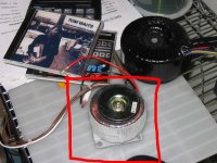
As my semi-final Quasi (I planned this along time ago) amp I will make 5 plate amps, each with its own supply, heat sink, transformer, PCB and heat sink. I found the "baby" Toroidal just the other day! They are pulled from a series of subwoofer amplifiers and they are very compact and I guess each may deliver 80~120VA so one per board would be nice. Of course this all goes into one big fat case and delivers the love to the theatre set-up.
Cheers,
Shawn.
quasi said:R6 needs to be changed for different rails.
> 60 volts R6 = 18K
30 - 60 volts R6 = 6K8
less than 30 volts R6 = 0 ohms (link)
This must be done or the first stage won't work properly.
Cheers
Q
As my semi-final Quasi (I planned this along time ago) amp I will make 5 plate amps, each with its own supply, heat sink, transformer, PCB and heat sink. I found the "baby" Toroidal just the other day! They are pulled from a series of subwoofer amplifiers and they are very compact and I guess each may deliver 80~120VA so one per board would be nice. Of course this all goes into one big fat case and delivers the love to the theatre set-up.
Cheers,
Shawn.
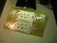
Attachments
Re: Plate amps
The smallest Quasi's will only have 4 Fets per amp, Q, does that change anything more on the previous post ?
Cheers,
Shawn.
The smallest Quasi's will only have 4 Fets per amp, Q, does that change anything more on the previous post ?
Cheers,
Shawn.
Quasi
All I have is a PDF is there more documentation?
Is the Amp design finalized?
I read where you were going to release another board?
Is there a parts list, Are boards going to be made? Group Buy?
Thanks
All I have is a PDF is there more documentation?
Is the Amp design finalized?
I read where you were going to release another board?
Is there a parts list, Are boards going to be made? Group Buy?
Thanks
Re: Quasi
The number of FETs does not change anything other than the power handling. All other components stay the same for the voltages used.
I thought the amp design was finalised until Shawn found an error recently. I will post corrected layouts soon. This will be the only other board for this amp I will release.
I do not intend making any PCB's or commercialising this amp. You are welcome to take any of the designs I have posted on this thread and give them to anybody to make PCB's for you. If someone organises a group board buy that's cool too. Note though I would be very dissappointed to learn that someone was making a profit from things that I have developed. My entire intention apart from building my own amps, is to provide other DIY'ers with projects that work well and are royalty free.
The downside is that I cannot provide a fully detailed project document only what I have posted and emailed already. This for most people should be enough. If it isn't then they need to seek help on this thread or from a friend.
Cheers
Q
TomWaits said:The smallest Quasi's will only have 4 Fets per amp, Q, does that change anything more on the previous post ?
Cheers,
Shawn.
The number of FETs does not change anything other than the power handling. All other components stay the same for the voltages used.
ppcblaster said:All I have is a PDF is there more documentation?
Is the Amp design finalized?
I read where you were going to release another board?
Is there a parts list, Are boards going to be made? Group Buy?
Thanks
I thought the amp design was finalised until Shawn found an error recently. I will post corrected layouts soon. This will be the only other board for this amp I will release.
I do not intend making any PCB's or commercialising this amp. You are welcome to take any of the designs I have posted on this thread and give them to anybody to make PCB's for you. If someone organises a group board buy that's cool too. Note though I would be very dissappointed to learn that someone was making a profit from things that I have developed. My entire intention apart from building my own amps, is to provide other DIY'ers with projects that work well and are royalty free.
The downside is that I cannot provide a fully detailed project document only what I have posted and emailed already. This for most people should be enough. If it isn't then they need to seek help on this thread or from a friend.
Cheers
Q
Hi Quasi,
I realise the readers will not allow you to sign off.
This seems my opportunity to thank you for all the sterling work you have put into this design project for the good of the DIY community.
Thank You
regards Andrew T.
I realise the readers will not allow you to sign off.
This seems my opportunity to thank you for all the sterling work you have put into this design project for the good of the DIY community.
Thank You
regards Andrew T.
Attention Shawn;
Hi Shawn,
Your piccy in post #1020 shows 2 x polarised capacitors used in the DC detect circuit where there should be 2 x non-polar (or bi-polar). Please change these or your life will gather some extra (a little) grief.
Cheers
Q
Hi Shawn,
Your piccy in post #1020 shows 2 x polarised capacitors used in the DC detect circuit where there should be 2 x non-polar (or bi-polar). Please change these or your life will gather some extra (a little) grief.
Cheers
Q
Your welcome Andrew;
As are all on this thread. A lot of the design in this amp is the result of a lot of input, especially early on, by other DIY'ers on this thread and also by email. So my thanks go to these people and to you for helping along the way.
Cheers
Q
As are all on this thread. A lot of the design in this amp is the result of a lot of input, especially early on, by other DIY'ers on this thread and also by email. So my thanks go to these people and to you for helping along the way.
Cheers
Q
Re: Attention Shawn;
Nice Eye! Thank you! Those actually belong in my momentary start switch circuit. I will correct it ASAP.
Thanks,
SHawn.
quasi said:Hi Shawn,
Your piccy in post #1020 shows 2 x polarised capacitors used in the DC detect circuit where there should be 2 x non-polar (or bi-polar). Please change these or your life will gather some extra (a little) grief.
Cheers
Q
Nice Eye! Thank you! Those actually belong in my momentary start switch circuit. I will correct it ASAP.
Thanks,
SHawn.
AndrewT said:Hi Quasi,
I realise the readers will not allow you to sign off.
I don't think Q could let go if he tried. 😉
This seems my opportunity to thank you for all the sterling work you have put into this design project for the good of the DIY community.
Thank You
regards Andrew T.
THANK YOU Mr. Q
Shawn.
- Home
- Amplifiers
- Solid State
- Power amp under development