Greetings, I have here a Power Acoustik A3000DB amplifier that is partially repaired and need some help to finish. I replaced the 16 PS Fets and the gate resistors and the 10 outputs. It currently powers up and produces +-65v or rail voltage. There is a toroid just in front of the regulators that is intermittently shorted but the high current draw goes away if I twist it right. When it was first powered up there was a square wave on the outputs when checked with a scope but it still produced audio to a test speaker. I replaced Q124, Q125, Q126, Q127 and Q113 on the preamp driver board and the square wave is no longer there, but there is no longer audio output regardless of how high I turn up the input signal. It has also shorted one output periodically like others have reported in their threads on here. I need to know how to get audio output again.
At idle with no signal the + bank of outputs has
Base: 0.0
Collector: +64.1
Emitter: 0.0
At idle with no signal the - bank of outputs has
Base: -63.8
Collector: 0.0
Emitter: -63.8
I have 5.0V across R175 on the driver board.
This amp has IC304 with pin 5 connected to speaker - and pin 6 connected to pin 6 on the driver board.
I can see what i think is music on pin 1 of the OPamp located on the driver board but I have no output on the speaker terminals. I can also see the fluctuating drive signal on the gate leg of the + outputs but the - outputs seem to be inactive when the volume is turned up.
QUESTIONS:
Can someone please help me find where the audio signal is getting lost and not reaching the speaker outputs please.
Should the - outputs have rail voltage on the gate leg?
Thanks.
Is pin 6 of the driver board switching from near rail to near ground a few seconds after remote is applied?
Pin 6 does not discharge when the resistor is applied across B+ and GND terminals. When I came back to the amp this morning it had approx. 5v showing. When I powered up the amp it jumps up to near rail voltage and then drops to near ground very quickly after. If i discharge the amplifier to 0v across B+ and GND, this pin remains at 8v.
Pin 6 of the driver board is on the secondary so discharging the primary voltage won't discharge it. When you power the amp on, pin 6 should go to near +rail voltage and remain there until the green LED goes red (although there were some variations of the initial start sequence). The amp cannot produce audio until pin 6 is driven very near 0v. IC 304 will read approximately 1.1v DC across pins 3 and 4. You will read approximately 0.2v DC across IC304 pins 5 and 6.
This has separate red and green leds. On startup, there is a slight delay, then the green led illuminates.
Something has changed since I started testing right now. I currently have 75.8v on pin 6 of the driver board and IC 304.
IC 304 had 1.08 across 3 and 4 and 0.18 across pins 5 and 6 when I first tested after reading your reply. Maybe I shorted something out...again.
On the driver board, pin 6 goes to a 47k resistor which tested in tolerance and is connected to a A1023 transistor which I had previously replaced because it was shorted. Removed and checked it again but it is good. Replaced it with another one with no change, still have 75v on pin 6. A1023 has 75.7 on Base, 66.2 on Collector and 75.6 on Emitter.
Currently reading 81v across pins 5 and 6 of IC 304 which is also pins 3 and 6 on the driver board. What component is responsible for pin 6 dropping to near 0v?
Pins 3 and 4 of IC304 control pins 5 and 6. When pins 3 and 4 have just over 1v, pins 5 and 6 should conduct and read approximately 0.2v. If you have 1v+ on pins 3 and 4 but high voltage across pins 5 and 6, IC304 is damaged. You can solder a bridge across 5 and 6 to force the output 'on'. This will defeat part of the protection so use caution if you short 5 and 6.
Ok, so I have 1.08v across pins 3 and 4, -.02v on pin 5, and 71.5v on pin 6.
By bridging pins 5 and 6 i would be forcing 71.5v into pin 5 of IC 304. What would happen next?
What is the purpose of IC 303? Could I swap IC 304 and IC 303? Is there a substitute for this TLP521-2?
What protection is being diasabled? What would I have to be very careful not to do?
By bridging pins 5 and 6 i would be forcing 71.5v into pin 5 of IC 304. What would happen next?
What is the purpose of IC 303? Could I swap IC 304 and IC 303? Is there a substitute for this TLP521-2?
What protection is being diasabled? What would I have to be very careful not to do?
You won't be forcing 70+v into pin 5. You will be pulling the voltage on the 47k ohm resistor down to ground. That switches on the driver board.
There are likely subs but the original should be available.
All protection would be disabled. As with any troubleshooting with the protection circuit disabled, you have to monitor everything (temp of components, current draw...) and be prepared to VERY quickly remove power from the amp if something is in danger of damaging components.
What is the purpose of IC 303? Could I swap IC 304 and IC 303?
If I do bridge pins 5 and 6, what am I looking for next?
Am I just connecting a speaker to see if I have audio output or are there readings I can take to ensure that everything is safe?
If the intermittent short in the toroid by the regulators happens to appear while pins 5 and 6 are bridged, would I be more likely to fry components even though I am using a mains testing current limiter?
303 is used for DC offset protection and regulation of the main rails so I would not operate it without 303 in the circuit.
Yes, look for audio output.
With the protection disabled, you have to watch every aspect of the operation.
There is no toroidal component near the regulators. Are you referring to the output transistors?
If so, having one inductor shorted is not good but won't cause instantaneous failure of anything. If both short, that could cause damage within a few seconds.
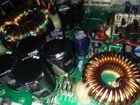
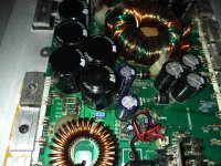
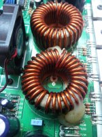
Not sure what it is called, or referred to as, but it is the non matching toroid on the board that is giving intermittent trouble with shorting. It is not the two matching inductors in front of the outputs and it is not the two similar toroids that are in front of the PS FETs. This one is the fifth toroid component on the board. I do not know what it is called or what its purpose is...
It's the filter inductor for the rails. The heatsink mounted components are rectifiers.
That's a very simple fix. The shorts are generally where the terminal windings meet the rest of the windings. Sliding an insulator of some sort between the windings will generally fix it unless the windings have been broken by the heat.
That's a very simple fix. The shorts are generally where the terminal windings meet the rest of the windings. Sliding an insulator of some sort between the windings will generally fix it unless the windings have been broken by the heat.
bridged pins 5 and 6 of IC 304 but still have no audio output. Have 1.08v across pins 3 and 4, and .013v across pins 5 and 6. Did have audio output yesterday before changing Q124 and Q125 when I saw square waves on the outputs. Square waves disappeared after the change but so did audio output. What to check next.
You can't have proper output without the square wave signal.
Are you sure that you didn't make any mistakes when replacing the driver board components?
Could you have pulled vias in the main board or on the driver board?
Broken traces?
Are you sure that you didn't make any mistakes when replacing the driver board components?
Could you have pulled vias in the main board or on the driver board?
Broken traces?
Where is that square wave produced and where can I find it? Is isn't the same wave on the rectifiers, right?
I will have to double check the driver board connections. Do you have any pics of the front and back for comparison? I did have one damaged trace that I reattached to where I think it went.
I will have to double check the driver board connections. Do you have any pics of the front and back for comparison? I did have one damaged trace that I reattached to where I think it went.
I have photos but none that show everything clearly in one photo. I'd have to see a photo of the location in question.
This is a self-oscillating amp so the square wave is produced by a function of instability when the servo loop is closed. It's not like a clocked class D amp where you can follow the signal from its source.
It's not the same as the power supply. In this amp, there is no relationship between the two oscillators.
What would cause this amp to overheat one of the rail capacitors until it smoked and leaked electrolyte onto the board. The amp was functioning normally all day and then spontaneously, with the volume low and engine idling, smelly smoke started to come out of the amp accompanied by popping noises. When I opened it up I found the rail cap closest to the outputs had cooked. The amp still turns on normally and all voltages at the components read ok. What would cause this to happen? Could it be IC303 or IC304 not functioning properly?
I got this amp working by changing the photocoupler at IC304 and running through the driver board thoroughly. I was unable to get the 8pin Dual Optocoupler so I used two 4pin substitutes from a local supplier. While testing IC304 and IC303 I had swapped them and possibly mixed them up so I am unsure whether IC303 has the bad TLP521-2 in it or not. On the bench with 13.6v/7A input the rail voltage was +/-67v, while it was +/-76v when it was in the vehicle with the battery charger connected and reading over +14v. The rail voltage remained equally balanced between +and-, and never increased, or spiked, beyond this while testing.
I got this amp working by changing the photocoupler at IC304 and running through the driver board thoroughly. I was unable to get the 8pin Dual Optocoupler so I used two 4pin substitutes from a local supplier. While testing IC304 and IC303 I had swapped them and possibly mixed them up so I am unsure whether IC303 has the bad TLP521-2 in it or not. On the bench with 13.6v/7A input the rail voltage was +/-67v, while it was +/-76v when it was in the vehicle with the battery charger connected and reading over +14v. The rail voltage remained equally balanced between +and-, and never increased, or spiked, beyond this while testing.
Attachments
Last edited:
Is the insulation on the terminal winding of the inductor in the left photo wearing through (powdery material between windings)?

- Status
- Not open for further replies.
- Home
- General Interest
- Car Audio
- Power Acoustik A3000DB issues