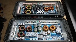
I got this amp for free but looks like someone has already tried to repair it. I have the same amp but is different. Posting photos. The one plays fine but the other powers up but no output. followed the signal to the driver board that uses IRS2110s. It has no modulation on pin 1 and pin 8. The signal seems to stop at the first TL072 and go square on pin 7.
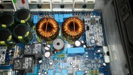
Are these the origonal ICs. The outputs are also different FDA59n25.
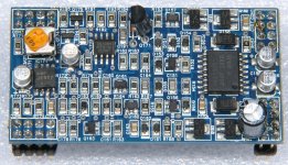
Pin 3 and 11 both have -105v using speaker ground.
Are these the origonal ICs. The outputs are also different FDA59n25.
Pin 3 and 11 both have -105v using speaker ground.
Attachments

Does your scope display a square wave properly? Those should be square. I don't know if it's your scope or the signal.
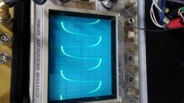
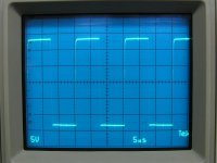
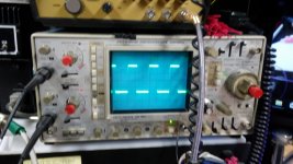
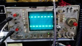
Attached are pins 1 and 7 as they should be.
Pin 1 drives the MPSW92 which drives the driver IC via a dozen or so other components. The collector of the W92 should have a drive signal that drives from the negative rail up about 10v.
Attached are pins 1 and 7 as they should be.
Pin 1 drives the MPSW92 which drives the driver IC via a dozen or so other components. The collector of the W92 should have a drive signal that drives from the negative rail up about 10v.
Attachments
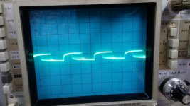
Not sure what was up with my scope. Maybe time to clean the knobs. I bought it used at a local electronic supply house. After some fine beating the image was better. Have to adjust those rabbit ears with aluminum foil.😀
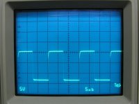
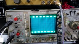
Attached is the correct readings.
sorry for not being in focus.
Attached is the correct readings.
sorry for not being in focus.
Attachments
It's OK as long as you're not the one wearing the aluminum foil hat.
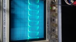
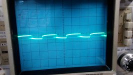
The combination of the two sets of images make it seem like it's OK. Mine were taken at 5v/div., 5us/div. and DC coupling. The drive for the W92 transistor is the one that is mainly below the reference. Are you getting a square wave drive to the driver IC?
For there to be modulation, you would have to see audio on pin 5 of IC172 and a triangle waveform on pin 6.
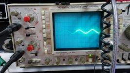
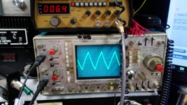
There is something going on. I am using a function generator for signal. Its output is at the lowest setting which has a output of .6v on the rca's. I have everything turned to the left(pic included). but with any adjustment to gain or crossover control the signal goes from pure to square, as in clipping. I am not sure what to make of that.
But I am getting the signals off of IC172.
Howerver I am not getting any signal to IC151 (IR2110s).
But I am getting the signals off of IC172.
Howerver I am not getting any signal to IC151 (IR2110s).
Attachments
reset the scope to dc coupling and still get the same. Not sure if its a flaw in the scope or what. Quite possible.
I don't see how you can get a signal that swings positive and negative when the drive signal is all negative.
😡okay. going to deoxit on the scope. that is going to drive me crazy. Think i will drown it in a 55 gallon of de-ox-it. Then light a match. HeHe! Be back soon, I hope😉
No drive signal on collector of W92. Just -105v.
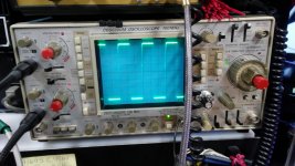
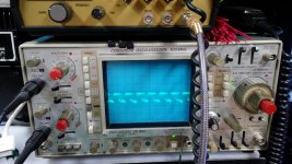
The two images are W92 pins 1 & 2
The waveform does change a bit if i increase volume or decrease volume. More of a duty cycle than amplitude.
The two images are W92 pins 1 & 2
The waveform does change a bit if i increase volume or decrease volume. More of a duty cycle than amplitude.
Attachments
Last edited:
Check DZ71 and Q71.
You should have 15v across DZ71 and about 15v on the emitter of Q71. Place the black probe on the negative rail when measuring the voltage on the emitter of Q71. You can also measure across C156 near the 2110. DZ71 and Q71 are the supply for pins 3and 11.
You should have 15v across DZ71 and about 15v on the emitter of Q71. Place the black probe on the negative rail when measuring the voltage on the emitter of Q71. You can also measure across C156 near the 2110. DZ71 and Q71 are the supply for pins 3and 11.
Okay, The TIP41 was shorted as well as the Zener diode. I cant make out what the part number is on the zener. do you have the part number? Or what the voltage is for the zener?
- Home
- General Interest
- Car Audio
- power Acoustic BAMF 5500.1d powes up no output