Wondering if there is a way I can use a pair of 4.4K opt to get 20-30Wpc from this board. Too sleepy to grind through 1000+ posts right now and too much of a neophyte to puzzle it out for myself. (If I had to guess at how to skin this cat I'd be looking for a tube that was happy with a lower load...but that approaches WAG status).
Wondering if there is a way I can use a pair of 4.4K opt to get 20-30Wpc from this board.
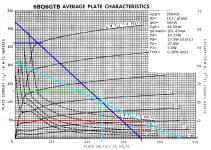
Yeah, there is. See attached loadline. 6BQ6GTBs or 6BQ6GAs can do nearly 40W, and can stand up to the spec busting without any problems. (That's what I had: junkbox Stancor OPT rated at 30W, 4K4 (P-2-P) primary, 4/8/16/125/500R secondary -- seemed intended for Class A 6L6s?) I did a project that's similar to this one, but with a different front end (cascode LTP + cathode follower grid drivers) that worked really well.
Attachments
Thanks Miles. I emailed you about Le Renard a couple weeks or so ago. I've got another project to finish up in the next couple of weeks and depending on how that turns out we'll see if I go with EL34 (triode or pentode?) or 6BQ6GTB. Many factors in deciding which. I don't think either one would cost significantly more than the other given that I have the EL34 already. There is definitely a large appeal in going with the sweep tubes in a circuit built around iron with the same specs as what I have.
Looking at the power transformer I have:
P: 117V@ 1.8A
S: 140V@ 0.85A AC
S: 6.3V@ 4.4A
S: 6.3V@ 3.8A
S: 48V@ 0.13A DC
Am I right that I could use this with a voltage doubler and get the necessary B+ but that it wouldn't exactly work with the big red board?
It also appears that this wouldn't really allow me any B+ beyond that for the stock DCPP and I would therefore be limited to the ~18wpc of the stock build?
thats only 200v after rectification. Its not much and ive only seen people run them at 270 or higher. with a doubler thats closer to 400 which is 75 volts higher then stock. About the only trick you can do to get higher watts with stock voltage, is to replace the tubes with beefer models, and then lower the output load to 4k-3k. This would get you to 40-50watts.
Can one use a choke input on a voltage doubler?
If so, then you can drop the voltage with it.
If so, then you can drop the voltage with it.
OK, in PSUD2 I set up a very simple PS with 140DC secondaries off the transformer as a solid state voltage doubler. I get ~340V on the cap and resistor immediately after the diodes (which is dead on what the schematic calls for). Where am I going wrong? Do I need to divide 140 by 0.7 to go from RMS AC to DC or something? That gives ~400V. Along with all that, how can I figure out the amp rating after the voltage doubler?
ya ant going wrong. You are correct. My est was in perfect land. Amp rating should be half what the transformer is rated for since your are doubling the voltage. Still your caps must be massive to voltage double for a 80-100 watt amp.
I am using a voltage doubler on a 120 VAC transformer in a guitar amplifier that I am designing in this thread:
http://www.diyaudio.com/forums/instruments-amps/190738-hundred-buck-amp-challenge.html
I get 322 volts and my amp draws about 100 mA. A 140 VAC transformer should then make 340 to 360 volts depending on what the actual secondary voltage is under load. Minor deviations from the 340 volt spec are not a problem in the red board even with the stock tubes. I ran my board up to 450 volts with the stock tubes. No problem as long as you have a good heat sink on the mosfets.
Yeah, that is the common wisdom. I never listen to what people tell me, so I just did it. It works, but you need two chokes, one in series with each diode.
Another thing that people told me won't work....use an old dual primary power transformer for the choke. Connect one primary winding in series with each diode. Don't connect any secondary to anything. Try swapping the leads to ONE of the primary windings and choose the connection that gives the lowest DC output voltage under load. This trick only works if the currents through each primary winding are equal and out of phase. That will be the case in a voltage doubler if you don't tap off any direct (undoubled) voltage. I have done this and it works, but as always YMMV.
http://www.diyaudio.com/forums/instruments-amps/190738-hundred-buck-amp-challenge.html
I get 322 volts and my amp draws about 100 mA. A 140 VAC transformer should then make 340 to 360 volts depending on what the actual secondary voltage is under load. Minor deviations from the 340 volt spec are not a problem in the red board even with the stock tubes. I ran my board up to 450 volts with the stock tubes. No problem as long as you have a good heat sink on the mosfets.
Can one use a choke input on a voltage doubler?.....nope v doubles are 2.8x vac. cant choke till after rectification, and by that time...
Yeah, that is the common wisdom. I never listen to what people tell me, so I just did it. It works, but you need two chokes, one in series with each diode.
Another thing that people told me won't work....use an old dual primary power transformer for the choke. Connect one primary winding in series with each diode. Don't connect any secondary to anything. Try swapping the leads to ONE of the primary windings and choose the connection that gives the lowest DC output voltage under load. This trick only works if the currents through each primary winding are equal and out of phase. That will be the case in a voltage doubler if you don't tap off any direct (undoubled) voltage. I have done this and it works, but as always YMMV.
Ive seen used power transformers wired as chokes. Never thought of using a dual primary for 2 chokes.
Thanks folks. The output iron I have on hand is from a 25wpc amp. Am I right that with 4.4K OPT's and ~335V B+ I'm in the ballpark?
I just found the walk-through of the 6BQ6GTB amp that Miles wrote up on a different forum. Wow!! Here I am trying to muddle through understanding what is going on and I find that. Wonderful.
I just found the walk-through of the 6BQ6GTB amp that Miles wrote up on a different forum. Wow!! Here I am trying to muddle through understanding what is going on and I find that. Wonderful.
At 4.4k and 335v you are looking at double the output of petes design. You would have to check with the other members if you can use the stock tubes at 4.4k. I know you can double the output with stock tubes by increasing voltage, not sure about just lowering the load. I know for sure it will work with 6hj5's as output tubes.
I know that the stock tubes aren't the best choice given the power limitations and primaries of my iron. I was looking for something else that would be happier with 4.4K @ 25W. Miles suggested the 6BQ6GTB (which is octal). At this point I'm leaning towards his design but nothing is set in stone. I'm just now starting to beginning to understand how to set up load lines and to determine operating points. It is a bit harder (for me) with the TV tubes because the datasheets have somewhat different information / format than tubes expressly intended for AF amplification. FI, the 6HJ5 sheet from RCA has no graphs. Hard for me to figure out what its gonna do on my own. Wanna learn though 🙂
there is several graphs in this thread on the 6hj5's. They will work stock all the way down to 3.3k and 600v. The are a plug in match, but you have to move 2 resistors on each socket. There is a pick of this too. Or i can post another one.
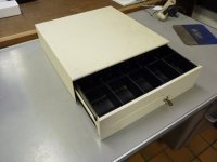
Interesting DIY Chassis
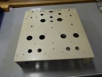
I'm building the 6HJ5/6GU5 version with two Antek AS-2T230s; one for board power, one for boost. Antek AN-0240 for the bias. Edcor 100W 5K/8ohm outputs. I jumper clipped the circuit together to make sure it worked. All that iron needs a good size chassis. Low and behold sitting right in front of me on the junk shelf were some old defective cash drawers. Voila, instant chassis. After cutting all the holes in this thing I now remember why I am not particularly fond of a steel chassis. I'll post more as I move forward.
I'm building the 6HJ5/6GU5 version with two Antek AS-2T230s; one for board power, one for boost. Antek AN-0240 for the bias. Edcor 100W 5K/8ohm outputs. I jumper clipped the circuit together to make sure it worked. All that iron needs a good size chassis. Low and behold sitting right in front of me on the junk shelf were some old defective cash drawers. Voila, instant chassis. After cutting all the holes in this thing I now remember why I am not particularly fond of a steel chassis. I'll post more as I move forward.
Attachments
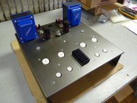
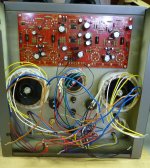
Now all I have to do is wire it up. This amp is heavy.
Concerning the heatsink, with that much steel it's really a moot point. But hey I think it looks cool. 😀
Alright, I read the whole thread start to finish. It seems like Big Red is a definite option for me. Maybe y'all could check what I think I know here...
I have output transformers that weigh 4.6 pounds, have 4.4K primaries, and were used in a HK amp rated at 25W output using 7355s. I have the power transformer from the same amp (described in post 1064) which I would use with a voltage doubler to get a B+ somewhere in the vicinity of 330V. I think I'm more than fine on current draw but I'd appreciate a nod on that. The power tranny weighs about 8.5 pounds (bigger than the stock Edcor FWIW). All three transformers were made by Magnetic Windings of Easton, PA. It appears that this puts me in the 30-40 watt per channel range. I would probably use 6HJ5, 6AV5 or 6GY5 but it seems like I have lots of options here. Given what others have done with this board it seems like it would be a fairly straightforward and conservative build. Am I missing anything?
FWIW, I have small kids. This thing will live up out of reach AND have a cage over it. It'll probably be ugly though. I always seem to stop when something is working well and never get to the bit about making it beautiful.
Also...Has anyone actually tried 6GY5 in the circuit yet?
- Home
- Amplifiers
- Tubes / Valves
- Posted new P-P power amp design