kct
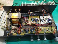
What can I say, beautiful work !! First thing I always look at is wiring inside the amplifier 😀
No wiring = no problems. Really great work.
Some of DIYers are spending a lot of effort and time to build a nice piece of amplifier. All is nice made, then messy/random placed wiring goes on top of the hard work 🙁
Thanks borys, I am glad you like my second Tribute Project.🙂
I don't understand it either, I guess the wire part comes down to how far one wants to take it and individual preference or perhaps the ability to use CAD tools in an efficient matter. Probably most guys on here are true hobbyists and may not even have CAD layout tools or enough experience to use them to the full potential. Perhaps CAD tools they use have nagging limitations or they are too focused on laying out 100% symmetrical boards and so loosing sight of the bigger picture. Or perhaps, actually thinking about how to do board to board connection is not as glamorous and sexy as theorizing about IPS, CCS, current mirrors and stuff. 😀
I totally agree, the classic wire mess is a nice invitation for trouble. I try to avoid it. But there is a distinct advantage to it, one is totally -flexible- 😀 to solve an interconnect issue, provided the magic smoke is still in there...
But then, it's a hobby after all. 🙂
kct
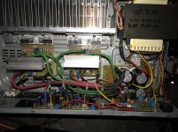
IMHO it is very important to plan very well the new ''build'' , it is DIY so there is no rush, all the work can be done nice and slowly.
Connections are a weak points so it is good practice to eliminate as many of them as possible.
Let me say the the amplifier from post above #6121:
-amplifier boards can be placed flat on the rear wall = shorter cables to the OP trannies
-potentiometers can be integrated with the tone board = no cables, short path, no corroded/oxydated pins after a few years
-two bridge rectifiers can be placed on the left = short AC current's path
-maybe turn the transformer 90deg (not sure) = the screening copper band should short rest of the magnetic flux coming out the transformer ?
- input RCA = it would be better to place them far from the transformer and AC mains
-ground the chassis and place the V+ V- bus just by the floor
I know that it might be not necessary but it will look a bit more tasty. Small little things but all together can make a big difference.
kct
IMHO it is very important to plan very well the new ''build'' , it is DIY so there is no rush, all the work can be done nice and slowly.
Connections are a weak points so it is good practice to eliminate as many of them as possible.
Let me say the the amplifier from post above #6121:
-amplifier boards can be placed flat on the rear wall = shorter cables to the OP trannies
-potentiometers can be integrated with the tone board = no cables, short path, no corroded/oxydated pins after a few years
-two bridge rectifiers can be placed on the left = short AC current's path
-maybe turn the transformer 90deg (not sure) = the screening copper band should short rest of the magnetic flux coming out the transformer ?
- input RCA = it would be better to place them far from the transformer and AC mains
-ground the chassis and place the V+ V- bus just by the floor
I know that it might be not necessary but it will look a bit more tasty. Small little things but all together can make a big difference.
Hi borys,
yes, I agree the design you referenced is a classic prime example of a nice rats nest with all the bells and whistles a good rats nest should have. 😉 I mean it's a hobby for most of us anyway. But this is a great documented example and testament of ability, skill and level of understanding by the creator at the time of creation. Today the creator may have a better understanding, skill and ability may have dramatically improved, but then sometimes -not, some people like to keep to -tradition- and so remain on a certain level. Perhaps proud has something to do with this also.
The world we live in today is literally upside-down in many ways, what used to be right has become wrong and what used to be wrong has become right these days. With that in mind, perhaps it can be explained why such sad examples draw a large fan base which throws good money and good parts at such inferior designs and yet they are very happy doing that.
I guess all reference has been lost completely 😕
Heck even authors in this space publish sometimes really good rubbish, and yet these books are 'best sellers'. Go figure.🙄
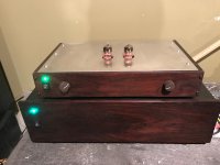
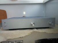
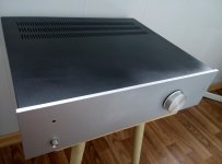
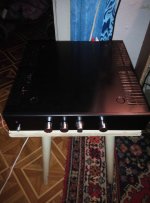
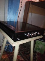
Rmi-fc100 with ldr pre, ultimate integrated combination. Completely operated by remote, no buttons whatsoever on the front panel.


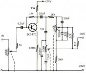
Retro Amp AX6
This looks good!
What is the preamplifier-tone control used here?
This looks good!
What is the preamplifier-tone control used here?
Preamp is Retro with 18V single suply and 2 transistors per channel
Attachments
Last edited:
First Build NMOS200
Hats off to Quasi and all those who contributed to this design.
This is my first build and from scratch too. I salvaged quite a few of the parts from dead receivers I snagged. The sound quality of this amp is excellent.
Hats off to Quasi and all those who contributed to this design.
This is my first build and from scratch too. I salvaged quite a few of the parts from dead receivers I snagged. The sound quality of this amp is excellent.
Attachments
I present my power amplifiers
Attachments
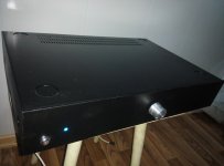
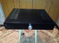
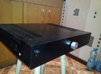

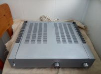
Some more photos of my products
Attachments
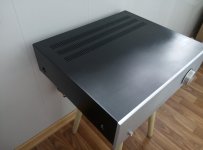
Same as I thought. Yes, we´d rather see the inside!Interior photos without cover.
- Home
- Amplifiers
- Solid State
- Post your Solid State pics here