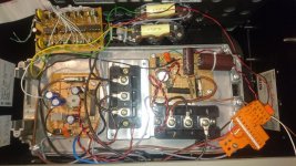
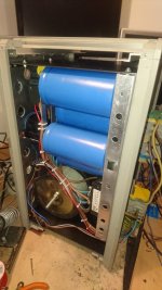
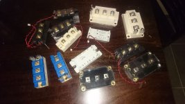
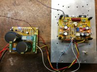
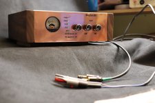
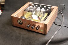
IGBTs amplifiers built with scrap parts from induction motors inverters and welding station. 200W / channel @4ohms, 100V supply
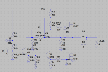
Very simple 2 transistors driver, diagram based on JLH1969 available for who want it.
1200W 150A IGBT...
Very simple 2 transistors driver, diagram based on JLH1969 available for who want it.
1200W 150A IGBT...
Attachments
Hello riritronic, please post the schematic, I'm looking for a big-balls amp for an 18" open baffle setup. Thanks!
Hello riritronic, please post the schematic, I'm looking for a big-balls amp for an 18" open baffle setup. Thanks!
Never tested above 110V supply.
Q1 : I use BC556, Q2: 2n5294.
Protect IGBTs by fast fuse, large amount of current during turning on. I supply it trough resisor for 10 seconds to avoid destroy IGBT.
Set bias potentiometer to maximum and decrease it slowly to set bias to 50 - 500mA depending of your IGBT.
Adjust offset pot to have half supply on output capacitor (be careful, decreasing output voltage increases bias current...)
You can replace the 100 ohms resistor by a PTC mounted on dissipator.
Attachments
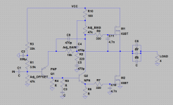
Diagram edited with missing values.
Output capacitor must be between 1500 & 10000µF splitted in 3 or 4 capa, I advice to use a 2.2 to 4.7µF plastic capacitor for high frequency to improve treble quality.
C10 & C11 are optional and must be used in case of oscillation (use smallest capacitor as you can)
Too muc gain increase instability (only 2 stages amplifier...). With high voltage supply (>70V) I recommand to add a fisrt stage with a gain of 2 to 5 made with OPamp or class A transistor pre-amplifier.
You can use parallel IGBTs or power half bridges
You can add antiparallel fast diodes on IGBTs
Attachments

Hello ...
Great build ..but for god sake I hate surface mount components they are fully banned from my workshop
but from what I have seen .. great work
Great build ..but for god sake I hate surface mount components they are fully banned from my workshop
but from what I have seen .. great work
Great job Borys!!
Thin film is the same as metal film in a small package. I’ve always had excellent results with thin film.
Ciao!
Do
Thin film is the same as metal film in a small package. I’ve always had excellent results with thin film.
Ciao!
Do
A few postcards from Ireland:
Very nice of course. But as a DIYer, how do you handle the soldering?
Hello ...
Great build ..but for god sake I hate surface mount components they are fully banned from my workshop
but from what I have seen .. great work
I second this!!!
I could never tackle SMDs.
So I'm curious about how a DIYer (not a rich one) can handle those tiny parts and the soldering...
It's well done, but I really want to know how it was done.
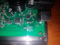
Larger SMD (1206) is very easy to solder with a conventional soldering iron, a hot air rework station or an oven. Passives are much easier to remove and replace than their through hole equivalent too.
To solder a resistor or capacitor in place dab some solder on one pad first, them set the part in place with tweezers and reheat the solder until the part sinks into place. Once the part is in place solder the other lead. To solder an IC put solder on one corner pad. Set the IC in place and reheat the solder until the part sinks into place. Once you have it aligned solder the opposite corner in place. Once you have it aligned and tacked down on two corners solder the rest. Any shorts between pins can easily be removed with a solder sucker or some solder wick. ICs are even easier using a hot air rework station and some solder paste because the IC will align itself.
The attached picture is a non audio project I assembled yesterday using mostly 0603 parts for an automotive application so it's loaded up with solder to minimize the chance of cracking due to vibration.
Attachments
Last edited:
This is a method to use of course, if you are "able" to do so, plus if you have some equipment and can afford it.
I could've done this some 30 years ago, but not now, and I suspect many are in such situation, where SMDs are just not feasible as a DIYer with limited means and especially with diminished physical capabilities (eyesight, steady hand...)
I could've done this some 30 years ago, but not now, and I suspect many are in such situation, where SMDs are just not feasible as a DIYer with limited means and especially with diminished physical capabilities (eyesight, steady hand...)
Anybody in this hobby has a soldering iron. Use an arm rest and a magnifying glass. I shake like a leaf and am almost blind in my right eye and this hasn't slowed me down. SMT is taking over the electronics world for many reasons besides cost. It's a superior technology when it comes to board layout. Much shorter traces make much quieter amplifiers.
Hi Jeff,
All true, but it takes a certain knack to lay out PCBs properly. You have that in spades my friend. I also know that no one can hold you back on something you have decided you're going to do.
But you are also correct. Most people can stuff PCBs with surface mount parts with a little effort. I can't see properly either, and my hands shake too. I do it with resting my arm. There is another factor to consider. You need a half decent soldering station and an assortment of tips for different soldering jobs. I've been known to use the 3mm screwdriver tip, but it isn't optimal by any stretch! I do generally change tips to something more suitable for surface mount.
The hot air station takes some practice to use properly, or all the small parts near a chip tend to desolder and run away. Just try and sort them out! I prefer 1206 and 805 sized parts. I'll complain about the 805's but not near as much as 603 sized parts. I can't even imagine trying to work with the smaller parts. I'm going to guess you should use a reflow oven for that stuff.
-Chris
Hi Chris.
That was all hand installed in about an hour with irons and hot air. I figured out a trick to keep things in place with the hot air rework station. Either install larger parts like ICs first or use standard solder to install the passives, then low temp paste for the ICs.
I always have two soldering stations running. One with a fine tip and one with a screwdriver tip. Any mistakes can quickly be removed by using the two irons like tweezers to pluck the incorrect part off.
another method I recently used to solder smds.
While laying out pcb whereever possible keep all smd's parallel to each other and of same size.
Then I got a smd holder 3-D printed.
placed it so that half the component is exposed. inserted smds and taped the holder. soldered one pad of smds.
voila! soldering was fun and a 5 minute job for 20 components.
no worry about shaky hands.
Ofcourse it may not be possible every time while designing the PCBs to have smds inline.
regards
Prasi
Attachments

I found soldering SMDs easier than THT and way quicker.
Three simple steps (as on the pictures):
Step 1:
Apply a bit of solder on the only one pad of each component
Step 2:
Solder every component at only one pad - use tweezers at one hand and soldering iron on the other hand
Step 3:
Solder second pad on every component on the board + correct the first pad if necessary.
Regards
EDIT:
And a few more post cards from Ireland.
Tomorrow is Paddy's day !! 😀😀😀
Attachments
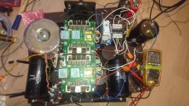
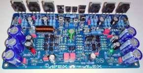
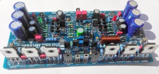
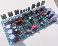
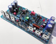
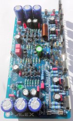
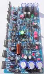
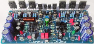
APEX A40 audio amplifier .
Attachments
-
 IMG_20180318_151000.jpg1 MB · Views: 535
 -
 IMG_20180322_130626.jpg835.1 KB · Views: 426
 -
 IMG_20180322_130649.jpg930.3 KB · Views: 235
 -
 IMG_20180322_130638.jpg835.4 KB · Views: 243
 -
 IMG_20180322_130710.jpg610.8 KB · Views: 244
 -
 IMG_20180322_130721.jpg592.9 KB · Views: 229
 -
 IMG_20180322_130557.jpg737.9 KB · Views: 280
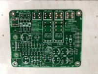
Hello guys I have this new speaker protection design I think my layout skills are a bit better and I learn a lot from Mr. Alex MM work 🙂 Mr. ST also is gonna build this one too
not tested yet wish me luck
Protection
time delay
DC offset
thermal
Best Regards
Juan
not tested yet wish me luck
Protection
time delay
DC offset
thermal
Best Regards
Juan
Attachments

- Home
- Amplifiers
- Solid State
- Post your Solid State pics here