JDS Labs Objective 2 Amp DIY Kit-- first build
First post here-- hello!
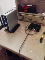
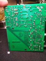
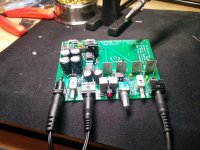
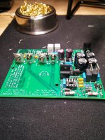
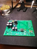
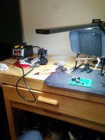
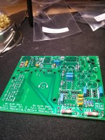
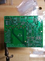
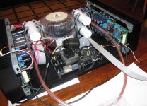
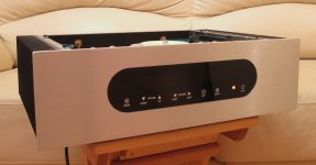
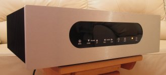
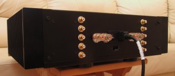
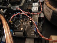
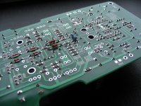
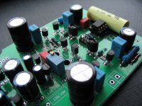
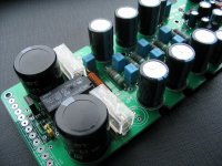
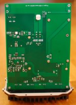
Attached are some pics detailing my journey building the Objective 2 amplifier using the JDS DIY kit. I had a great time building this and really feel like I honed my soldering skills over the course of the work. Happily, I had no errors during the resistance or voltage testing and the amp required zero troubleshooting. I was very diligent to be sure there were no shorts/cold soldered joints as best I could during the build. I also tested each component I could before stuffing it to the board. The amp sounds excellent with my Sennheiser HD-650s-- very neutral and perfectly clean. I have a Bottlehead Crack kit that finally shipped and should be in late next week-- I'm excited to compare the two!
I forgot to add-- I'm having my brother print me a custom faceplate on a 3d printer--- the plan is to have glow in the dark indicator text/markings and potentially backlit with a few LEDs-- we'll see what happens with that.
First post here-- hello!
Attached are some pics detailing my journey building the Objective 2 amplifier using the JDS DIY kit. I had a great time building this and really feel like I honed my soldering skills over the course of the work. Happily, I had no errors during the resistance or voltage testing and the amp required zero troubleshooting. I was very diligent to be sure there were no shorts/cold soldered joints as best I could during the build. I also tested each component I could before stuffing it to the board. The amp sounds excellent with my Sennheiser HD-650s-- very neutral and perfectly clean. I have a Bottlehead Crack kit that finally shipped and should be in late next week-- I'm excited to compare the two!
I forgot to add-- I'm having my brother print me a custom faceplate on a 3d printer--- the plan is to have glow in the dark indicator text/markings and potentially backlit with a few LEDs-- we'll see what happens with that.
Attachments
-
 IMG_20150120_214526.jpg599.2 KB · Views: 1,368
 -
 IMG_20150124_132552.jpg611.3 KB · Views: 320
 -
 IMG_20150124_130416_nopm_.jpg859.4 KB · Views: 410
 -
 IMG_20150124_125929.jpg910 KB · Views: 451
 -
 IMG_20150124_112153.jpg916.9 KB · Views: 259
 -
 IMG_20150122_232651.jpg889.3 KB · Views: 258
 -
 IMG_20150122_232705.jpg537.4 KB · Views: 1,012
 -
 IMG_20150122_215041_nopm_.jpg833.7 KB · Views: 1,094
 -
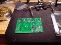 image.jpg599.3 KB · Views: 1,169
 -
 IMG_20150120_214850.jpg638.7 KB · Views: 1,260
Last edited:
Most DC servos inject a signal into the -IN input of the amplifier they are monitoring.
Any DC servo that does this is in the audio path.
That's why I commented , that IPS does not inject a signal to either +/- inputs.
It shifts the common reference for the 2 opposing CCS's.
PS - with a "failure mode" resistor in case the IC is faulty or missing. 😀
"2'nd generation servo-ing techniques"
OS
Final touches ....
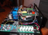
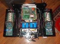
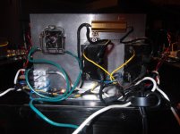
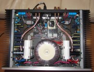
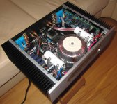
Having kids and others near a "deadly amp" requires some safety measures.
Rod Elliot's " high current ground fault interrupter " and power/softstart relay's.
(attachment 1) ....
Just a few specs ...
-1KVA 50V transformer
-82Kuf total capacitance / 73V rails
-200+ W per CH (at least) - 8R with overload and DC protect.
-Full programmable soft-start , external power-on trigger .
--- vzaichenko " 21'st century protection" Real cool - "bomb proof" !! 😀
-"Leach" type front end (like a HK990-)
can be swapped with any forum input
topology.
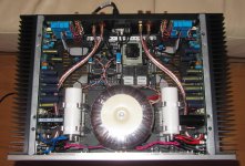
Attachments 2/3/4 are the "real pictures" of a really tightly packed pro- amp.
Time to sonically "level" the living room - ( break the china) 😀 .
OS
Having kids and others near a "deadly amp" requires some safety measures.
Rod Elliot's " high current ground fault interrupter " and power/softstart relay's.
(attachment 1) ....
Just a few specs ...
-1KVA 50V transformer
-82Kuf total capacitance / 73V rails
-200+ W per CH (at least) - 8R with overload and DC protect.
-Full programmable soft-start , external power-on trigger .
--- vzaichenko " 21'st century protection" Real cool - "bomb proof" !! 😀
-"Leach" type front end (like a HK990-)
can be swapped with any forum input
topology.
Attachments 2/3/4 are the "real pictures" of a really tightly packed pro- amp.
Time to sonically "level" the living room - ( break the china) 😀 .
OS
Attachments

Member
Joined 2009
Paid Member
Great work!Having kids and others near a "deadly amp" requires some safety measures.
Rod Elliot's " high current ground fault interrupter " and power/softstart relay's.
(attachment 1) ....
Just a few specs ...
-1KVA 50V transformer
-82Kuf total capacitance / 73V rails
-200+ W per CH (at least) - 8R with overload and DC protect.
-Full programmable soft-start , external power-on trigger .
--- vzaichenko " 21'st century protection" Real cool - "bomb proof" !! 😀
-"Leach" type front end (like a HK990-)
can be swapped with any forum input
topology.
Attachments 2/3/4 are the "real pictures" of a really tightly packed pro- amp.
Time to sonically "level" the living room - ( break the china) 😀 .
OS
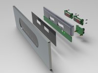
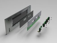
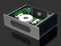
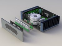
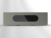
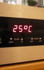
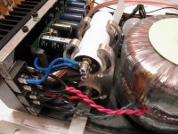
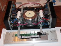
Hello world, here is my amp:
- 2 x 250W @ 4Ohm
- 2 x 330W toroidal transformers with low induction (1,35 T)
- 35 000 uF per channel
- 5 inputs
- Relay attenuator (Range - 128dB. Step - 1, 2, 3, 4 or 5dB)
- 7-segment LED display indication: volume level, selected input, temperature, balance
- DC protection
- Temperature protection (adjustable range for )
- Soft-Start
- Touchscreen with 8 sensor buttons
- RGB LED on main panel for on/off status indication
Weight – approx. 23-25 kg
Project (designed with Solid Works) & result:
Attachments
more pics
Attachments
-
 IMG_9673.jpg864.4 KB · Views: 419
 -
 IMG_9676.jpg368.7 KB · Views: 305
 -
 IMG_9681.jpg963.1 KB · Views: 354
 -
 IMG_9683.jpg661.3 KB · Views: 397
 -
 IMG_9694.jpg825.1 KB · Views: 384
 -
 IMG_9696.jpg577.8 KB · Views: 318
 -
 IMG_9704.jpg616 KB · Views: 439
 -
 IMG_9702.jpg583.9 KB · Views: 401
 -
 IMG_9700.jpg477.7 KB · Views: 372
Nice to share pictures. They are awesome!
But kind of useless when the source is not DIY.
Would you share it too?
But kind of useless when the source is not DIY.
Would you share it too?

Nice to share pictures. They are awesome!
But kind of useless when the source is not DIY.
Would you share it too?
Not DIY ?? 😕
It could be ... quite easy to do a mixed through-hole / SMD and have it cheaply
produced by a chinese board house.
Even the microprocessor controller could (most likely) be "in-house".
(some actually have SMD workstations).
The DIYA hobbyists are making this transition now.
OS
Nothing wrong with building a rig using pre-assembled modules, or even from kits. Many of us love the process of putting it all together and having it just work. Nothing wrong with the 'parts swapper' either trying to wring out that last bit of sonic perfection. I get tremendous satisfaction of building electronics - at any level.Nice to share pictures. They are awesome!
But kind of useless when the source is not DIY.
Would you share it too?
Absolutely stunning work Michael. I like someone who won't settle for anything less than perfection! Pictures probably don't do it justice. 🙂Amp PCB:
My new Project A-S.E.B. amplifier. It really sounds better than my previous Project A (It was presented within this exact thread several years ago).
Class A with no overall feedback, single ended balanced output, embedded AC/DC power supply:
Class A with no overall feedback, single ended balanced output, embedded AC/DC power supply:
Attachments


Last edited:

Nice to share pictures. They are awesome!
But kind of useless when the source is not DIY.
Would you share it too?
Are you kidding me?

This is DIY taken to another level.
My new Project A-S.E.B. amplifier. It really sounds better than my previous Project A (It was presented within this exact thread several years ago).
Class A with no overall feedback, single ended balanced output, embedded AC/DC power supply:
Great enclosure design! 🙂
- Home
- Amplifiers
- Solid State
- Post your Solid State pics here