A 4ohms rated amplifier should easily drive a 2r0 test load. This 2r0 test load stresses the output stages less than a very reactive 4ohms speaker load......................That delivers 500W per channel into 4 Ohms. I never had the guts to try it on a 2 ohm load - it also used 10 trannies per channel which is not quite enough...............
I would test an 8ohms rated amplifier into a 2r0 test load as a matter of course, to prove that the PSU does not collapse when delivering high current.
The tests (8 Ohm and 4 Ohm) were done with resistive loads. The 8 Ohm power was actually 280 W.
I don't agree that a 2 ohm load is easy to drive. This would imply something of the order of 1 kW into the load with 5 out put devices. To close for comfort.
Highly unlikely BTW that the PSU's in there amps will collapse. That a trick commercial amps do ;-)
I don't agree that a 2 ohm load is easy to drive. This would imply something of the order of 1 kW into the load with 5 out put devices. To close for comfort.
Highly unlikely BTW that the PSU's in there amps will collapse. That a trick commercial amps do ;-)
Bonsai,
Andrew is right, concerning the 2r load.
A reactive load consisting of 4 ohm and 45degrees phase angle (real speaker), will bring you in many cases closer to the SOA curve than a pure resistive 2R load. The non conducting side of the OPS will have to deliver a lot of current while having the entire rails voltage between collector and emitter.
PS: your PDF documents about your amplifiers are great!
Bensen, I know that . . .
My amplifiers were tested on resistive loads only.
I simply stated I had no desire to push the Ovation 250 to 1kW output :-0
My amplifiers were tested on resistive loads only.
I simply stated I had no desire to push the Ovation 250 to 1kW output :-0


@ DQ828: Too good.
Thanks, broke the bank & the will to live getting them finished🙂
It then depends on whether you have a 4ohms capable amplifier, or an 8ohms capable amplifier. It sounds from your reservation on SOA for the 5pr output stage that you are not claiming 4ohms capability. Have you tried Bensen's SOA spreadsheet, or do you have an alternative SOA modeling method?The tests (8 Ohm and 4 Ohm) were done with resistive loads. The 8 Ohm power was actually 280 W.
I don't agree that a 2 ohm load is easy to drive. This would imply something of the order of 1 kW into the load with 5 out put devices. To close for comfort.
Highly unlikely BTW that the PSU's in there amps will collapse. That a trick commercial amps do ;-)
If it's 280W into 8ohms, then a minimum test load I would use would be 2r0, but more probably 2r67 to check Vpk when 1/3 rated impedance is connected.
post2746
As stated : very nice.
I would double insulate the mains voltage wiring, not the LV wiring.
Another unhelpful post?
As stated : very nice.
I would double insulate the mains voltage wiring, not the LV wiring.
Another unhelpful post?
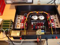
This is a my diy amplifier based on LME49810 high fidelity power amplifier driver. I used a discrete output stage with MJE15032/3 and two pairs MJ15003/4.
The schematic used you can find in driver's PDF. I designed my own layout with separate signal GND of power GND.
The power source is a full-bridge power converter based on ETD49 core.
Pulse modulator control circuit is provided by SG3525 and NCP5181 are power mosfet driver. Without power factor corection.
Soft start is realized by the SG pin 8 capacitor.
Switching power is made with a remote control socket. I transfered the socket's pcb in my enclosure.
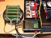
The ampl was tested with a dummy load ( five resistors 27 ohms/100W connected in paralel mod).
Unfortunately, my DS203 signal generator can't give a output signal more then 1Vrms.
The sound is great.
The schematic used you can find in driver's PDF. I designed my own layout with separate signal GND of power GND.
The power source is a full-bridge power converter based on ETD49 core.
Pulse modulator control circuit is provided by SG3525 and NCP5181 are power mosfet driver. Without power factor corection.
Soft start is realized by the SG pin 8 capacitor.
Switching power is made with a remote control socket. I transfered the socket's pcb in my enclosure.
The ampl was tested with a dummy load ( five resistors 27 ohms/100W connected in paralel mod).
Unfortunately, my DS203 signal generator can't give a output signal more then 1Vrms.
The sound is great.
Attachments
post2746
As stated : very nice.
I would double insulate the mains voltage wiring, not the LV wiring.
Another unhelpful post?
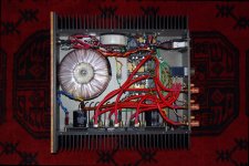
The idea was to shield the signal wiring, the RED cable has a braided copper & foil shield, I stripped out the center core & ran all of the signal wires through them
. But you are right on the double insulation for the mains, I should have done that as well.
It then depends on whether you have a 4ohms capable amplifier, or an 8ohms capable amplifier. It sounds from your reservation on SOA for the 5pr output stage that you are not claiming 4ohms capability. Have you tried Bensen's SOA spreadsheet, or do you have an alternative SOA modeling method?
If it's 280W into 8ohms, then a minimum test load I would use would be 2r0, but more probably 2r67 to check Vpk when 1/3 rated impedance is connected.
I am quite happy that it will deliver 500W into 4 Ohms (heatsink/thermal limits) and drive 2 Ohms load peaks for short periods). I am just not happy driving 2 Ohms for extended periods. This is a very capable amp.
test into 2r0 is not a heatsink test.
I consider it to be a current capability test.
That "current capability" does not need to be proved over one minute, not even for ten seconds.
One second is long enough for the PSU to droop to it's final value and for the output voltage to be measured/recorded while driving the dummy load.
It's a test I do on all my amplifiers. Check the maximum unclipped voltage into a load that is 1/3 (one third) of the rated impedance. I expect all my amplifiers to be within 1dBV of the maximum voltage into the rated load. Some will mange -0.4dBV and I use this information to judge the current capability. This test is quite different from driving a near short circuit to determine peak output current at near zero output voltage.
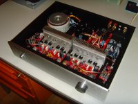
Did I already post a picture of my latest build?
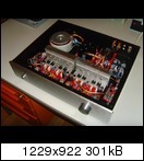
http://www.abload.de/img/symasym001dkknk.jpg
It is a SYMASYM, which I will give to my brother as Christmas present.
It consists of: a single power supply (2 x 25 VAC / 300VA toroid, DX power supply PCB with 40.000µF in total), two TO264-SYMASYM PCBs
with 2 pairs of NJW0281G / NJW0302G each, George Stantscheff's Lighspeed Attenuator being controlled by a motorized 100K
BOURNS potentiometer (the control PCB being inspired by FOTIOS), a cheap (50€ !) and nice chinese case, ...
And it is DIY.
For example: the infrared detector is glued to the front plate by 2 stripes of Wrigley's chewing gum. So this build has my DNA 😀 !
And it sounds like the second-to-best amplifier that I have ever listened to.
Best regards - Rudi_Ratlos
Attachments
......And it sounds like the second-to-best amplifier that I have ever listened to......
Best regards - Rudi_Ratlos
Which one is the best you have listened to ?
Cheers.
Ashok: I will give you a "diplomatic" answer to not affront any designer, who has published his amplifier in this forum. They are all the best!
But: Mihai's (ROENDER) FC-100 is a very outstanding amplifier.
Best regards - Rudi
But: Mihai's (ROENDER) FC-100 is a very outstanding amplifier.
Best regards - Rudi
- Home
- Amplifiers
- Solid State
- Post your Solid State pics here