Still recapping my ReVox B226
next caps that are going to be replaced include the post regulator decoupling caps;
Concerning those I've had contradictory advice... replace or leave the old ones? Brand new low ESR caps would perform bad in that position? I'm confused.
The old caps are Frako, they are 30 years old, it seems to me logical to replace them. But the circuit itself has been conceived 30 years ago, and the regulator chips are from stone age. so there might be some truth in the assumption that high ESR caps would perform better, for what reason I don't know.
So, leave the old, dried out caps? Change for good caps? Change for brand new, low quality caps?
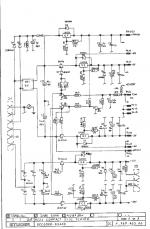
(caps are C2, C6, C8, C9, C13, C15)
here's schematics of the B226 PSU.
next caps that are going to be replaced include the post regulator decoupling caps;
Concerning those I've had contradictory advice... replace or leave the old ones? Brand new low ESR caps would perform bad in that position? I'm confused.
The old caps are Frako, they are 30 years old, it seems to me logical to replace them. But the circuit itself has been conceived 30 years ago, and the regulator chips are from stone age. so there might be some truth in the assumption that high ESR caps would perform better, for what reason I don't know.
So, leave the old, dried out caps? Change for good caps? Change for brand new, low quality caps?
(caps are C2, C6, C8, C9, C13, C15)
here's schematics of the B226 PSU.
Attachments
Last edited:
Change the caps! Use whatever caps you prefer. I recommend Panasonic FC series for the regulator.
If you are afraid the regulator chips are too old why not replace them with LM317/LM337 ?
If you are afraid the regulator chips are too old why not replace them with LM317/LM337 ?
Change the caps! Use whatever caps you prefer. I recommend Panasonic FC series for the regulator.
If you are afraid the regulator chips are too old why not replace them with LM317/LM337 ?
That's what they are: LM317, LM337. Are those subject to aging?
When I said "they're from the stone age" it's because I assumed (?) that there are better regulator chips now, but I don't know...
I'm not an expert but I read that low ESR are not good after old regulator (78xx/79xx/lm317/337 ...).
I would change them to new high quality but not low ESR electro 😉 in 22-100uF range: silmic 2, nichicon kg/kz, etc
I would change them to new high quality but not low ESR electro 😉 in 22-100uF range: silmic 2, nichicon kg/kz, etc
That's what they are: LM317, LM337. Are those subject to aging?
When I said "they're from the stone age" it's because I assumed (?) that there are better regulator chips now, but I don't know...
A lot of manufacturers produce the LM317 chips. I am not aware how the performance has improved over the years, but do not worry about it. They do not need to be changed.
Change all electro caps with suitable replacements. Use film caps in the signal path where possible (for values under 4,7uF usually) and also make sure that all contacts are clean. Relays used in the signal path should also be replaced as they also have a limited lifetime.
Op-amps ( if used in this machine ) are going to be an improvement if you use modern day low noise like OPA1612A or OPA2132
I'm not an expert but I read that low ESR are not good after old regulator (78xx/79xx/lm317/337 ...).
I would change them to new high quality but not low ESR electro 😉 in 22-100uF range: silmic 2, nichicon kg/kz, etc
So I can use the Silmic II that I planned to use there? that's good to know... 🙂
thanks for ur answer!
A capacitor at the output or a regulator interacts directly with the regulator output impedance, which is likely to be inductive and possibly resistively negative too in some frequency regions. A cap with sufficiently high ESR will damp any problems.
If you must change the caps (and this is probably unnecessary) then change like for like. If the cap was an ordinary cheap electrolytic then replace with an ordinary cheap electrolytic.
As I always say, in order to improve a circuit you need to understand it even better than the original designer.
If you must change the caps (and this is probably unnecessary) then change like for like. If the cap was an ordinary cheap electrolytic then replace with an ordinary cheap electrolytic.
As I always say, in order to improve a circuit you need to understand it even better than the original designer.
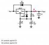
Output capacitor in the LM317
Beware of capacitor with low ESR.
But my experience is easy to solve the problem
At the out leg of the LM317 add low-value resistors 0.47 to 1 ohm
Then the output capacitor can be valued at up to 1000UF .
That way you solve the problem of modern capacitors with low ESR.
Just dont forget to add a protection diode -if the output capacitor are big value
220-1000uf
Attachments
Last edited:
A capacitor at the output or a regulator interacts directly with the regulator output impedance, which is likely to be inductive and possibly resistively negative too in some frequency regions. A cap with sufficiently high ESR will damp any problems.
If you must change the caps (and this is probably unnecessary) then change like for like. If the cap was an ordinary cheap electrolytic then replace with an ordinary cheap electrolytic.
As I always say, in order to improve a circuit you need to understand it even better than the original designer.
What kind of problems can it create?
This morning I replaced the original 47uF 10V with silmic II same value, same rating.
I don't hear any noise or "nasties", but the sound seems to be less mellow and more upfront. Less "bloom".
That said, I will wait a bit for the caps to settle in. So far they only played around 45 minutes!
What kind of problems can it create?
oscilation for instance ; too much high impedance in the high end...etc !
This is at the output of the reg. Near the load is an other story, you want lower ESR here. The example is given by Dazz member. It's works even better with the more Noisy 78/79xx regs ! LM317 is a pretty good chip, even if there is better now, but as you see, all is about the layout .
As writted DF96 member, it is not by chance you have these yellow caps here. If you can find the old datasheet, you could understand what the engineer wanted to do here. As already said that is not saying you can't do better, at least adapt to your taste... but the warning is also you could do worst !
Two basic rules : one change at once then listen.... and if not good don't hesitate to come back to the previous conf 🙂
on
78xx
79xx
output
i use low pass filter
resistor 10 ohm 470uf cap low ESR RUBICON ZLK/ZLJ
78xx
79xx
output
i use low pass filter
resistor 10 ohm 470uf cap low ESR RUBICON ZLK/ZLJ
Attachments
-
 12525093_3159015697584_7690047113477346895_o.jpg302.7 KB · Views: 262
 -
 12593798_3159014617557_8757462045911408493_o.jpg113.6 KB · Views: 291
 -
 12525631_3159015377576_3774082668473638029_o.jpg203.2 KB · Views: 247
 -
 12378010_3159015337575_6077119945614194756_o.jpg172.7 KB · Views: 219
 -
 1501055_3159014777561_8139342857652441593_o (1).jpg244.6 KB · Views: 219
Last edited:
Oscillation in really bad cases. A rise in regulator output impedance in milder cases, possibly accompanied by a noise peak. In some cases no problem at all.KanedaK said:What kind of problems can it create?
In some cases it is easier to avoid creating the problem by simply leaving the old cap in place. Rise in ESR is one of the failure mechanisms of an electrolytic, so why replace an old one with a slightly high ESR with a new one plus a resistor? Note that the added resistor should be in series with the cap, not the regulator output; otherwise you degrade the regulation.dazzz said:But my experience is easy to solve the problem
At the out leg of the LM317 add low-value resistors 0.47 to 1 ohm
Then the output capacitor can be valued at up to 1000UF .
That way you solve the problem of modern capacitors with low ESR.
Oscillation in really bad cases. A rise in regulator output impedance in milder cases, possibly accompanied by a noise peak. In some cases no problem at all.
In some cases it is easier to avoid creating the problem by simply leaving the old cap in place. Rise in ESR is one of the failure mechanisms of an electrolytic, so why replace an old one with a slightly high ESR with a new one plus a resistor? Note that the added resistor should be in series with the cap, not the regulator output; otherwise you degrade the regulation.
Voltage And Current Regulators
3 - IC Regulators
IC (3-terminal) regulators are now the most common of all analogue/ linear types. For many years we had the 78xx (positive) and 79xx (negative) regulators, and there were several common voltages available. 5, 8, 12, 15, 18 and 24V versions were available, but these have rationalised to just 3 - 5V, 12V and 15V. Adjustable regulators (LM317/337) allow people to build a power supply for almost any voltage they like, from as low as 1.25V up to 50V if you use the high voltage versions.
They are convenient, and the fixed regulators are also available as low power versions in a TO-92 package. The 78L05 is particularly common, as it can provide regulated power for small micro-controllers, PIC based projects and other low power logic circuits. The internal circuitry of these ICs is now quite advanced, and they are capable of very good performance. They all have short circuit protection, and include internal over-temperature cutouts so they are almost indestructible ... almost !
The common 78xx/79xx series regulators are often considered 'inferior' by many audio enthusiasts, but this isn't justified. Yes, they are somewhat noisy, but the typical noise output is low-level and will very rarely cause a problem with opamp circuits. It's worth noting that the output capacitor is needed primarily for stability, and without it the regulator will probably oscillate. It doesn't matter if it's 10uF or 1,000uF, the output ripple will not change.
This apparently odd behaviour is due to the output impedance of the regulator. According to the datasheet for the 7815, it has an output impedance of 0.008 ohm (8 milliohms) at frequencies up to 1kHz, after which it rises at 6dB/octave. At 100Hz, a 1mF (1,000uF) capacitor has a reactive impedance of 1.59 ohms, and that has absolutely no effect against the 8 milliohms of the regulator. The output impedance remains below 1 ohm at any frequency up to 1MHz, and at the frequency extremes a capacitor will have some effect.
Ripple rejection is stated to be a minimum of 54dB (7815) with a typical value of 70dB. Typical output noise is claimed to be 90uV. An easy way to improve the noise and ripple voltages is to add a simple resistor/capacitor filter at the output of the regulator. For output currents of 100mA or less, a 10 ohm resistor and 1,000uF cap will reduce the output voltage by 1V at 100mA, but will reduce 100Hz ripple by another 16dB (minimum). It will also reduce wideband noise. At 1kHz, any regulator noise is reduced by 36dB, and 56dB at 10kHz. Combined with the already low noise and ripple, the residual is negligible. Predictably, this technique can only be used successfully at comparatively low currents.
It is also possible to use a filter consisting of an inductor and capacitor, but great care is needed to ensure that the -3dB frequency is well below the ripple frequency or you can easily end up with more ripple instead of less! For example, an LC filter consisting of a 1mH inductor and 1mF (1,000uF) capacitor has a frequency of 159Hz, and increases ripple by 4dB. Increasing the inductor to 10mH results in a ripple reduction of 10dB, and also rapidly attenuates all frequencies above 50Hz. Ideally, the inductor (or capacitor) should be larger, and any LC filter is sensitive to the load impedance and may cause transient ringing with varying loads - great caution is advised!
Small Power Supplies
Using 10 ohm series resistors from the supply with 1,000µF caps to ground for each polarity, noise is almost completely eliminated. The supply voltage is reduced by only 100mV for each 10mA of current drawn which will not affect any audio circuit. This is a far cheaper option than using a relatively expensive discrete power supply that requires exotic opamps and costly 'audio grade' capacitors and other components. The noise can be expected to be reduced by at least 60dB with this simple filter. High frequency noise (the most intrusive, and least affected by the opamp's PSRR) is affected the most by the filter. Note that it is pointless adding a large cap without a series resistor - the output impedance of most regulators is so low that it will have almost no effect.
Last edited:
oscilation for instance ; too much high impedance in the high end...etc !
This is at the output of the reg. Near the load is an other story, you want lower ESR here. The example is given by Dazz member. It's works even better with the more Noisy 78/79xx regs ! LM317 is a pretty good chip, even if there is better now, but as you see, all is about the layout .
As writted DF96 member, it is not by chance you have these yellow caps here. If you can find the old datasheet, you could understand what the engineer wanted to do here. As already said that is not saying you can't do better, at least adapt to your taste... but the warning is also you could do worst !
Two basic rules : one change at once then listen.... and if not good don't hesitate to come back to the previous conf 🙂
Hmm...
well according to what I read, Silmic II have much higher ESR than typical "low ESR caps", specially at low voltage ratings.
I don't like the idea of 30 years old frako caps in there. Before I started recapping this player really sounded rough and dirty; i could feel it had potential, but it was nowhere near as good as I was expecting (considering its reputation of being a fine player), so I assume the caps were pretty much about to die.
I will keep the silmic at least until they're fully burned in, then I'll see; if it sounds good, it's good, no? i keep the old caps around, just in case.
Now I will just re-post the PSU schematics again: if you guys could have a peek for me in there and tell me if ReVox used a circuit that's prone to instability of it's been taken care of (after all, they're ReVox).
Note that I only replaced C2 C6 C8 C9 with silmic II.
I didn't touh C13 and C15 yet. Those are 22uF 10v frako.
Note that I only replaced C2 C6 C8 C9 with silmic II.
I didn't touh C13 and C15 yet. Those are 22uF 10v frako.
Attachments

Hmm...
well according to what I read, Silmic II have much higher ESR than typical "low ESR caps", specially at low voltage ratings.
I don't like the idea of 30 years old frako caps in there. Before I started recapping this player really sounded rough and dirty; i could feel it had potential, but it was nowhere near as good as I was expecting (considering its reputation of being a fine player), so I assume the caps were pretty much about to die.
I will keep the silmic at least until they're fully burned in, then I'll see; if it sounds good, it's good, no? i keep the old caps around, just in case.
I believe just the main PS caps needed to be replaced... perhaps !
Yes keep the old caps, just in case... btw Nothing is better than experiments, so you are on the right pass.
dazzz said:Predictably, this technique can only be used successfully at comparatively low currents.
Same idea; different words. At low currents you are probably not too worried about good regulation.DF96 said:Note that the added resistor should be in series with the cap, not the regulator output; otherwise you degrade the regulation.
Only IC4 and IC5 are feeding the analogue stage and here you may put audio grade capacitors after the regulators. For other regulators in this particular player, you may use either general purpose electrolytics or low impedance ones. I have never heard anyone having problems with oscillating regulators in B226. As already mentioned, circuits are at a considerable distance from the PSU, so there will be sufficient ohmic and inductive resistance, too. I have personally used tantalums with double voltage rating after digital voltages regulators IC1-IC3.
... but on the "analog" regs you may have even better results if they are at more than 10 cm from the power supply to add this "audio grade" (said often to be low esr) at the input of the reg and not the output. For instance a Nichicon KZ is just horrible at the output of such regs despite it's audio grade !
Personnaly I find the solid tantalum to play good as said at the output of these old regs if digital path. It plays the "resistive" game but without loss of information at ears... (sorry to add the subjective to the "technical"... just my own experience!)
Personnaly I find the solid tantalum to play good as said at the output of these old regs if digital path. It plays the "resistive" game but without loss of information at ears... (sorry to add the subjective to the "technical"... just my own experience!)
- Status
- Not open for further replies.
- Home
- Source & Line
- Digital Source
- Post regulator caps... old or new?