there was a 6v6 pp amp used the 6au6 pentode drivers with output plate to plate/cathode feedbacks to the 6au6 drivers and not using any over all global feedback....
i believe MilesPrower also had one such amp using the 6bq6gt tubes and ltp cascode voltage amp stage....
i believe MilesPrower also had one such amp using the 6bq6gt tubes and ltp cascode voltage amp stage....
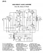
Maybe you were thinking of this one (from the RCA Receiving Tube Manual RC-19 1959).
I also found this schematic of the Trimax A45 Monitoring Amplifier in my collection/database.
I also found this schematic of the Trimax A45 Monitoring Amplifier in my collection/database.
Attachments
Hello TonyTecson and all. Thank you all for this enlightening/teaching thread. The author did a great job explaining the schematic of your post and its nuances. My following question may be a stupid one; never asked or yes and humbly expected from a novice like me.
What if feedback is routed from the top output pentode to the bottom phase splitter tube [6AU6]? Ditto for the bottom power pentode to the preceeding upper splitter [6AU6]. Totally instead of that shown; or partially in conjunction with it. Will there be any subjective or objective performance value or worse; a detriment?
A scope picture is valuable for the added understanding for such an amp; which juxtapositions the signals at either phase splitter; to grasp the signals' phase and amplitude relationships.
Best wishes
Anton
Last edited:
I would think that the negative feedback than turns into positive feedback, probably turning the amplifier into an oscillator.
A performance value may emerge from using a balanced extent for each of positive and negative feedback.
here is a tip, if what you think has no one else doing it, then probably it does not work...
i also have lots of ideas, so i go around the net to look for prior art, finding none, it probably is not worth it....
today, the challenge is to improve upon the existing topologies using different tubes and better parts...
we do not worship a cult of originality for originalities' sake....we improvise, we upgrade, we make better what someone else did before us...no shame in that...
Last edited:
Hello TonyTecson and all. Thank you all for this enlightening/teaching thread. The author did a great job explaining the schematic of your post and its nuances. My following question may be a stupid one; never asked or yes and humbly expected from a novice like me.
What if feedback is routed from the top output pentode to the bottom phase splitter tube [6AU6]? Ditto for the bottom power pentode to the preceeding upper splitter [6AU6]. Totally instead of that shown; or partially in conjunction with it. Will there be any subjective or objective performance value or worse; a detriment?
A scope picture is valuable for the added understanding for such an amp; which juxtapositions the signals at either phase splitter; to grasp the signals' phase and amplitude relationships.
Best wishes
Anton
you are making an oscillator
A performance value may emerge from using a balanced extent for each of positive and negative feedback.
I certainly don't know everything about feedback yet so please read the following with that in mind.
There are ofcourse examples of amplifiers in which there is both positive and (more!) negative feedback going on at the same time. Here are two of them:
- 7199:RCA Application Notes
- see pages 23 to 28, 67 to 71 and 85 to 93: http://www.introni.it/pdf/Rodenhuis%20-%20HiFi%20Circuits.pdf
In these cases the combination of positive and negative feedback has a specific purpose, like extending the low end of the frequency response (first example) or to achieve more gain in the preamplifier/inverter (second example).
But in the RCA amplifier in post #43 the mix you suggest would not serve a specific purpose unless you would introduce some form of frequency dependent feedback. But that would come at a price, like a lower damping factor at the low frequencies, etc..
I would think that if you want the amplifier to keep the same gain, than a certain amount of positive feedback has to be compensated by a same amount of negative feedback. The endresult would therefore be zero.
Last edited:
here is a tip, if what you think has no one else doing it, then probably it does not work...[I humbly and inventors may differ].
i also have lots of ideas, so i go around the net to look for prior art, finding none, it probably is not worth it..... [Ideas are hypotheses for optional validity testing]
today, the challenge is to improve upon the existing topologies using different tubes and better parts...[Fully agree; plus possibles injecting new approaches]
we do not worship a cult of originality for originalities' sake....we improvise, we upgrade, we make better what someone else did before us...no shame in that.. [I full agree and celebrate your forward looking approach]Thanks TonyTecson for replying and dialoging.
Best wishes
Anton
I certainly don't know everything about feedback yet so please read the following with that in mind.
There are ofcourse examples of amplifiers in which there is both positive and (more!) negative feedback going on at the same time. Here are two of them:
- 7199:RCA Application Notes
- see pages 23 to 28, 67 to 71 and 85 to 93: http://www.introni.it/pdf/Rodenhuis%20-%20HiFi%20Circuits.pdf
In these cases the combination of positive and negative feedback has a specific purpose, like extending the low end of the frequency response (first example) or to achieve more gain in the preamplifier/inverter (second example).
But in the RCA amplifier in post #43 the mix you suggest would not serve a specific purpose unless you would introduce some form of frequency dependent feedback. But that would come at a price, like a lower damping factor at the low frequencies, etc..
I would think that if you want the amplifier to keep the same gain, than a certain amount of positive feedback has to be compensated by a same amount of negative feedback. The endresult would therefore be zero.
Thank you PFL200 for your clear insights. Your links and those of the members contributing to this thread are a valuable [and living] teaching assignment for me [and others] to learn this new [to me] language of vacuum tube circuits.
I grasp and appreciate [celebrate too] the vast experience and knowledge of and offered by all of this thread's contributors.
Best wishes
Anton
Observation: I could not dowload the PDF link.
Last edited:
you are making an oscillator
Thanks TonyTecson. You and other contributors to this thread [less I] speak from experience and knowledge. I accept your answer and the earlier one like it by PFL200 to be accurate.
Scope pictures of signals I had suggested from/in such amplifiers can augment teaching/understanding it. They are not found in the links describing the amps' works. Detail detail..
Best wishes
Anton

You are using a differential cascode front end with feedback superimposed on the cascode voltage? I'm trying something similar, but with solid state assistance. It's been on the back burner for a while as I've been working on other things, so not actually tested yet. I used an RC network to let me set feedback ratio independently of DC voltage without using separate supplies. Probably will cause stability issues. We shall see....
Attachments
Hello egellings. Thanks. Found the schematic of the HK Citation II on HiFi Engine. Does have multiple feedback loops. It uses overall NFB plus the intra negative feedback which is discussed in earlier posts.
You are using a differential cascode front end with feedback superimposed on the cascode voltage? I'm trying something similar, but with solid state assistance. It's been on the back burner for a while as I've been working on other things, so not actually tested yet. I used an RC network to let me set feedback ratio independently of DC voltage without using separate supplies. Probably will cause stability issues. We shall see....
Hello tikiroo. Thanks for the schematic. You have the power of LTSpice to generate simulated scope signals at the recipient components possibly before and after feedback.
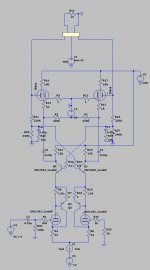
Here is my experimental Class AB2 PP 6V6 amp with internal NFB from circa 2000. I has been on DIY in the past a few times.🙂
Hello jhstewart9. Thanks for the schematic. It projects both of your experience and knowledge. Was there a thread on it for me to follow?
- Home
- Amplifiers
- Tubes / Valves
- Possible to do feedback from before OPT on PP amps?