At what frequency were those measurements made?
Those were 1kHz measurements.
Don't forget the Citation II.
Do you by chance know the B+ of that circuit? I'd like to run some sims.
The key is low-impedance drive. Whether it is achieved through local FB or inherent topology does not matter.I have heard this claim about OPT distortion but has anyone really quantified the distortion of a typical OPT driven by the lowish impedance of an output stage with local feedback? If they are so horrible then a lot of zero gNFB amps ought to sound really bad and trying to force them into linearity with FB might indeed lead to some wickedly difficult wave forms in the transformer itself perhaps causing its own problems.
A regular tube PP stage without FB has high output impedance, and is maximally affected by the transformer's non-linearity, but that is precisely something tube-sound-lovers are looking for: in fact, the tube sound is mostly "iron" sound, and it bears similarities with the semi + iron sound, either in the fifties/sixties style, or with more modern approaches, like Pass's ones
That's a kind of a dilemma: how do you get good objective, numerical performances without sacrificing the magical tube sound?
It is mostly a matter of personal taste
It certainly makes a difference. How much depends on the circuit specificsAlso I wonder about the tactic of using local FB before the OPT and then putting the secondary in the cathode circuit of the output tubes. The question of course is whether the cathode FB is sufficient to make any real difference.
These figures are interesting, but not really significant: with a transformer having a coupling coefficient of exactly 1, primary and secondary figures would be identical, but they would include the contribution of the core and the active elements, and there is no simple way to disentangle them, especially if the OP stage has a local FB.I have, in a 6384 SE amp with fairly heavy local feedback (so nice and low driving impedance on the transformer primary, less than 100 ohms for sure).
Distortion on OT primary:
100mW - 0.038%
500mW - 0.086%
1W - 0.12%
2W - 0.17%
5W - 0.28%
10W - 0.44%
Distortion on OT secondary:
100mW - 0.045%
500mW - 0.10%
1W - 0.14%
2W - 0.21%
5W - 0.35%
10W - 0.51%
This was with an Edcor 5k:8 25W transformer. I'd say the amplifier is definitely the main distortion component, but the transformer's distortion contribution is not insignificant, especially if you look at harmonic contribution. The OT adds significant higher-order harmonics at higher levels.
This means that you have no way to know in what proportion the iron and the tubes contribute to the total THD figure.
The increase seen at the secondary is just caused by the primary leakage inductance and the primary resistance.
The only way to determine reliably the transformer's contribution to the THD would be to test it in isolation, with a good test-amplifier.
Drive the secondary from the test amp with a series resistance equivalent to the 100 ohm input multiplied by 8/5000, and measure the THD for various excitation levels, at the primary or the secondary
The circuits I have in mind are push pull sweep tubes such as say ECL85, 6LR8 etc. in UL or triode mode with possibly an additional 10 or 20 dB of local feedback.
Indeed the best info would come from someone with the proper equipment to drive the OPT buy itself with various source impedances at various frequencies and output levels. I have seen Jensen data of this type on their line level OPTs but nothing for tube power OPTs. For what it is worth the distortion on the line OPTs is minuscule below saturation. My guess is that power outputs would be significantly higher.
Indeed the best info would come from someone with the proper equipment to drive the OPT buy itself with various source impedances at various frequencies and output levels. I have seen Jensen data of this type on their line level OPTs but nothing for tube power OPTs. For what it is worth the distortion on the line OPTs is minuscule below saturation. My guess is that power outputs would be significantly higher.
Member
Joined 2009
Paid Member
The benefits are avoiding the complex reactive elements of the OPT in the loop thus reducing instability issues and avoiding trying to beat the OPT into submission with wild signals under overload conditions.
Philosophically I would prefer to drive the OPT with a clean relatively low Z signal and let the OPT run free as it were. Perhaps plate to grid around the output tubes would be adequate but I am not sure how well that would work if driven by a LTP or Paraphrase.
Sounds like a good approach to me.
Implementation will be easiest in Class A.
Later versions of this SE amp with an 826 output tube ended up with .027% distortion at 1W on the transformer secondary. I raised the amount of feedback and I estimate the driving impedance on the primary to be under 20 Ohms, just based on the measured Zout on the secondary and the winding resistances. See my Corona amplifier thread for more details.
I don't know what the irreducible distortion in a typical output transformer is, but it appears that it is quite low at midband and normal listening levels. Things are going to fall apart if you try to drive a transformer at LF with levels more than it can handle, but we know this.
To answer your basic question, I think you can make a very nice PP amplifier without any feedback around the output transformer. That's basically what my Plitron Unity-Coupled amplifier is. 50% CFB Push-pull amp, no feedback from the secondary.
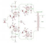
I've toyed with applying my Corona SE amp feedback scheme to push-pull amps, but making the feedback kind of like the input stage of an instrumentation amplifier (see attached).
I don't know what the irreducible distortion in a typical output transformer is, but it appears that it is quite low at midband and normal listening levels. Things are going to fall apart if you try to drive a transformer at LF with levels more than it can handle, but we know this.
To answer your basic question, I think you can make a very nice PP amplifier without any feedback around the output transformer. That's basically what my Plitron Unity-Coupled amplifier is. 50% CFB Push-pull amp, no feedback from the secondary.
I've toyed with applying my Corona SE amp feedback scheme to push-pull amps, but making the feedback kind of like the input stage of an instrumentation amplifier (see attached).
Attachments
A lot of Western Electric PP amps had feedback before the output transformer. WE 133A is one example. Purely symmetrical circuit. Very good sound, better than the 124.


Do you by chance know the B+ of that circuit? I'd like to run some sims.
Page 31 of the Citation II manual has a voltage chart for every pin on all the tubes. ( manual online) B+ was 450V.
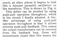
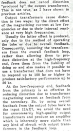
Norman Crowhurst wrote this about feedback from the primary in his Twin Coupled Amplifier:
https://www.audiofaidate.org/it/articoli/Crowth-twincoupled.pdf
https://www.audiofaidate.org/it/articoli/Crowth-twincoupled.pdf
Attachments
Later versions of this SE amp with an 826 output tube ended up with .027% distortion at 1W on the transformer secondary. I raised the amount of feedback and I estimate the driving impedance on the primary to be under 20 Ohms, just based on the measured Zout on the secondary and the winding resistances. See my Corona amplifier thread for more details.
I don't know what the irreducible distortion in a typical output transformer is, but it appears that it is quite low at midband and normal listening levels. Things are going to fall apart if you try to drive a transformer at LF with levels more than it can handle, but we know this.
To answer your basic question, I think you can make a very nice PP amplifier without any feedback around the output transformer. That's basically what my Plitron Unity-Coupled amplifier is. 50% CFB Push-pull amp, no feedback from the secondary.
I've toyed with applying my Corona SE amp feedback scheme to push-pull amps, but making the feedback kind of like the input stage of an instrumentation amplifier (see attached).
Hello SpreadSpectrum and all. This is an interesting and very well explained thread. Seems to me in your post above that the amp's damping factor is low in the absence of overall negative feedback. Is this OK? Would you call this consequent amp [and others like it in this thread] current or voltage source?
Thanks.
Anton
Poor Man's Definitions:
Current Source: Any change in the load resistance/impedance does Not change the amount of current in the load.
Voltage Source: Any change in the load resistance/impedance Does change the amount of current in the load.
Low Pass Filter: When the frequency going into the filter is increased, the higher the frequency is, the longer the delay is for the high frequency to get out of the filter.
The delay is so great for the very highest frequencies, so they never make the journey out of the filter.
Amplifier output classification:
All amplifier outputs are according to the following:
Current Source
Voltage Source
Resistive power source
Combination of two of those.
In the real world, resistance is present.
There are no perfect current sources
There are no perfect voltage sources
All of the above are just my opinions
(and I suspect a few other people's opinions too).
Last edited:
It is 20 Ohms driving impedance on the primary of the output transformer. That means that the amplifier Zout is almost completely dominated by transformer copper resistances. I measured 0.7 Ohms Zout on the 8ohm secondary, so a damping factor of over 10 which is unusually high for an SE amp.
Local FB is nicely documented around here in a whole lot of flavours. I'll second the notion that you decide to stay Class A. The amount of extra power offered is, IMO not worth going after. From a 25W EL34 amp, a 50W one is *JUST barely louder...
cheers,
Douglas
cheers,
Douglas
Member
Joined 2009
Paid Member
Norman Crowhurst wrote this about feedback from the primary in his Twin Coupled Amplifier:
https://www.audiofaidate.org/it/articoli/Crowth-twincoupled.pdf
+1
It is 20 Ohms driving impedance on the primary of the output transformer. That means that the amplifier Zout is almost completely dominated by transformer copper resistances. I measured 0.7 Ohms Zout on the 8ohm secondary, so a damping factor of over 10 which is unusually high for an SE amp.
Thanks SpreadSpectrum. A great DF value.
It is 20 Ohms driving impedance on the primary of the output transformer. That means that the amplifier Zout is almost completely dominated by transformer copper resistances. I measured 0.7 Ohms Zout on the 8ohm secondary, so a damping factor of over 10 which is unusually high for an SE amp.
Hello SpreadSpectrum. I am interested in vacuum tube power amps and their performance. My knowledge of this broad topic is embryonic. I experiment for entertainment. I am toying with mating a look-alike of a VT amp with a solid state one. This is found in the last post [and previous ones] of the thread 'Class aP amplification'/ Pass Labs Forum. Your thoughts [and others] on this experimental approach of study can only be valuable.
Best wishes
Anton.
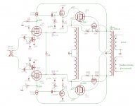
Two examples. The one with the 807's runs in class A. The one with the 7027A's (from a RCA Receiving Tube Manual) runs in class AB1.
You read my mind. 🙂
I was searching for that brilliant RCA design to answer the original question, but found it in this exactly thread. 🙂
- Home
- Amplifiers
- Tubes / Valves
- Possible to do feedback from before OPT on PP amps?