Yeah, I think the baffle was a molded plastic piece bonded to plywood or MDF underneath.Is there something like a foam baffle with holes for the drivers under the stretchy cloth?
As a DIYer, it was a bit fussy but not difficult. Best to build a 2 layer baffle, with the inside layer fitting into the enclosure & stopped to leave a wide enough gap. Needed my wife's help with the cloth & elastic.

Hi,
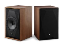
grill like that is nice as it doesn't add any frame which would reflect and diffract more than without the grill. But, I'm afraid the baffle edge is still there and the grill would not prevent sound reaching it so it's just for visuals, having same diffraction effects than any such box with hard edges.
The woofers don't likely show any bad diffraction effects as the baffle is relatively small compared to woofer size, and asymmetric, but the tweeter would diffract as sound gets to the baffle edge just like without the grill, and the edge is there relatively far away and the diffraction is there. There is even additional cutout/edge midway of the front, which also diffracts some.
I'm afraid if one wants monkey coffin outer dimensions, and use tricks to reduce diffraction, the front would need to be quite thick damping material, I mean like the whole top portion of the box, and shaped not like a box, so the monkey coffin idea get's easily ruined. Perhaps some more lightweight diffraction mitigation solutions works fine enough, reduce most audible effect, like some waveguide for tweeter. I don't know what is enough so perhaps make it the traditional way and live with it. For optimized diffraction do something else completely than rectangular box with multiple drivers and slap on fixes.
Having simulated some waveguides to weed out as much diffraction effects as possible it's first of all really difficult to get really good performance, and the achieved performance is ruined quite easily due to small tolerance issues manufacturing for example, or assembling the speaker with sloppy joints, and so on. Pretty good performance isn't too difficult though. Hence I suspect that slap on diffraction mitigation just shifts things around but doesn't really fix it, just makes it different.
For this reason, I think it would be best to go just full on visuals and fun project, and kind of forget about the diffraction at least not get stuck agonizing it. Except perhaps consider a waveguide. Some people already objected waveguides, so perhaps even skip that to keep it max fun easy access. Make some practical grill. It would be cool if there was some diffraction mitigating grill so, perhaps try that, it would be cool to see if such thing would work.
Hopefully this wasn't too negative message, wanted to keep it within what looks like reality from my small hobbyist experience on this subject.
Last edited:
If you want to mitigate diffraction in a traditional monkey box enclosure - with a grill - you have the option to start spreading it out as it progresses toward the baffle edge in addition to the waveguide solutions.
Attachments
I used a quarter round (1~1.5" radius) on my versions. Can't find good finished pics, but here's one of the baffle being installed. Roundover on this edge was smaller.grill like that is nice as it doesn't add any frame which would reflect and diffract more than without the grill. But, I'm afraid the baffle edge is still there and the grill would not prevent sound reaching it so it's just for visuals, having same diffraction effects than any such box with hard edges.
Well, I will defer to the grill experts here. I never use them and have not given much thought to a proper grill design.
I think the effects of diffraction in a cabinet design extend beyond considerarions of the peaks and dips seen in the on axis response. While these would be better not to be there the on axis response, are less of a performance factor in a midfield monitor used at 2m plus than it would be in a true nearfield design.With a passive crossover I can see there may be a case for choosing to optimise for grille on or off when seeking to use bumps and dips from edge diffraction to cancel bumps and dips from the drivers and crossover. The flexibility of an active crossover lessens this. Effectively removes if one is prepared to switch between grille on and grille off coefficients.
I have circled an area in the horizontal response in these measurements from Erin of the Wharefdale Linton on the Spinorma.org site.
This is where the other diffractions effects are seen and there is not a monotonic falling with frequency off axis, but a large portion of the response where the off axis starts to dominate and in some case peak above the on axis. This is not an insurmountable problem, as this speaker rates highly among a lot of listeners but it does end up needing a lot more subjective voicing to tailor the response so that off axis energy build up does not dominate or skew the frequency balance. For a passive crossover this requires a substantial parts bin or an expensive buy and try routine. An active design version could probably help to get an idea of what sounds good first before trying to match it with passive parts if a simpler speaker without much diffraction mitigation is decided for.
This is a nice illustration of the types of issues I hope we will be at the heart of the project. By including drivers on a flat baffle and waveguide versions in the same project the performance tradeoffs should become clear in a quantitative way rather than the ususual qualitative. Similarly the cost of keeping clean sharp edges discussed earlier with different configurations would also be quantified.
Perhaps I should add that the intention, at least on my part, is to address many, hopefully most, of these types of issue at the design stage with detailed 3d simulations before building. Measurement and listening after building is pretty much certain to raise one or two issues but they should be minor. If not the design objectives would need significant revision which would be interesting.
Perhaps I should add that the intention, at least on my part, is to address many, hopefully most, of these types of issue at the design stage with detailed 3d simulations before building. Measurement and listening after building is pretty much certain to raise one or two issues but they should be minor. If not the design objectives would need significant revision which would be interesting.
It is my belief that, in earlier days, DIY good voicing practice was to lower on axis response at 3kHz with a few dB. Precisely because of this.but a large portion of the response where the off axis starts to dominate and in some case peak above the on axis
@fluid
What about putting all HF and MF drivers behind the baffle? ie. mounted on the rear side of the baffle, and then with a 45” chamfer bit or 3/4” roundover from the front hole.
In conjunction with surface mounting the woofer, this would bring acoustic centres in the Z-axis closer together and may facilitate easier (less parts) XO design,
This would effectively create a waveguide for all drivers eg. HF, MF and negate the need for large roundovers from the baffle, making construction easier for all builders.
Last edited:
Yes, this is an unavoidable issue when crossing over a 5” cone driver to a 1” dome tweeter on a flat baffle.I think the effects of diffraction in a cabinet design extend beyond considerarions of the peaks and dips seen in the on axis response. While these would be better not to be there the on axis response, are less of a performance factor in a midfield monitor used at 2m plus than it would be in a true nearfield design.
I have circled an area in the horizontal response in these measurements from Erin of the Wharefdale Linton on the Spinorma.org site.
This is where the other diffractions effects are seen and there is not a monotonic falling with frequency off axis, but a large portion of the response where the off axis starts to dominate and in some case peak above the on axis. This is not an insurmountable problem, as this speaker rates highly among a lot of listeners but it does end up needing a lot more subjective voicing to tailor the response so that off axis energy build up does not dominate or skew the frequency balance. For a passive crossover this requires a substantial parts bin or an expensive buy and try routine. An active design version could probably help to get an idea of what sounds good first before trying to match it with passive parts if a simpler speaker without much diffraction mitigation is decided for.
View attachment 1424641
It even happens with a 4” driver.
Tons of spekers were build like that, even well kown studio monitors. That is not such a big issue. If you're nitpicking like for modern studio monitors it is, but for average hifi this is not the biggest problem.
I don't mind to develop with an active crossover first, but you need to keep in mind while designing a setup that it also need to work with a passive crossover. So no big bass boosts on the woofer and so.
And the mounting of some drivers on the back could be a good thing, as long as you can open the cabinet from the back. If you need to mount it before glueing it won't work. So maybe use a removable front panel like andy sugested in his tread.
Both make for pretty ordinary waveguides. A DXT or something similar works to narrow directivity a bit if it really must be minimal build complexity required.What about putting all HF and MF drivers behind the baffle? ie. mounted on the rear side of the baffle, and then with a 45” chamfer bit or 3/4” roundover from the front hole.
I might run some simulations when I can be bothered (no promises) to see how narrow a waveguide needs to be to have a significant enough affect on this size speaker with sharp edges, as I will need to know the answer at some point to decide how to make my own version.
Agree, I’m not thinking about the waveguide effect (ie. directivity shaping) but more as “protecting them” from baffle edge diffraction…
That available depth and width would be going towards one or the other, the best compromise as can be determined. I'd do the same. Several available dome/waveguide combinations end at an angle and are just asking for a baffle roundover as it turns out.. but it remains to be worked out.I’m not thinking about the waveguide effect (ie. directivity shaping) but more as “protecting them” from baffle edge diffraction…

That whole thing, including the cabinet depth, affects the directivity.
I am thinking of a simple roundover, into the baffle, where the midrange, or tweeter could mount, to effectively put it behind the baffle, and protect it from diffraction effects of a sharp baffle
Eg. Midrange mounting ATC employs:

I am thinking of a simple roundover, into the baffle, where the midrange, or tweeter could mount, to effectively put it behind the baffle, and protect it from diffraction effects of a sharp baffle
Eg. Midrange mounting ATC employs:

I suspect it’s more work to do that than to mount a waveguide from the front. Also bear in mind that standard sheet material thicknesses are not the same on both sides of the Atlantic. When you mount something from behind the baffle you will probably have screws going from front to back into the tweeter. The holes for them need yo be perfectly aligned and perpendicular. This was always an issue for OSMC builders.I am thinking of a simple roundover, into the baffle, where the midrange, or tweeter could mount, to effectively put it behind the baffle, and protect it from diffraction effects of a sharp baffle
I suggest going with drivers with inbuilt waveguide instead, many of which can be front-mounted.
An important consideration. Rear mounting drivers creates several complications in cabinet construction, and in the design of the cabinet. A high performance cabinet can be designed with very high stiffness, or with a carefully controlled stiffness and damping, but either way, dimensional tolerances of the internal cabinet structure must be tightly controlled. Removable panels complicate this.I suggest going with drivers with inbuilt waveguide instead, many of which can be front-mounted.
- Home
- Loudspeakers
- Multi-Way
- Possible monitor/monkey box/coffin group project