Hi all,
I not sure if I'm having a problem with this amplifier but I thought I would ask just in case anyone knows anything about this amp and issue.
I have to turn the gain up a very long way before getting any decent output from it.
I have a 4V head unit and have confirmed that it produces undistorted output at 4 Volts all the way up to it's highest volume position.
With the volume on 55 out of a possible 62 I have to turn the gain on the JBL up a hair more than 3/4 of it's total movement before the amp clips it's unloaded output, the range being a nominal 100mV to 6V.
It is connected to a sealed JL Audio 13w7 that can take all the power the amp can throw at it.
The issue is that with having to turn the volume up so high before reaching maximum power at 0dB, there is no headroom to tune the gain for a -10dB overlap and other amps in the car are incapable of accepting such a high level from the head unit without the gain adjustment bottoming out.
I notice the JBL can have a bass knob connected, mine was second hand and didn't come with one, would connecting the bass knob help by allowing what would effectively be more gain than the amplifier gain knob would allow on it's own?
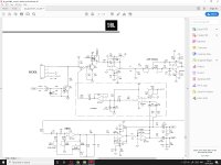
I attache a section of the schematic for your convenience, at this stage reading it is beyond me I'm afraid. 😱
I not sure if I'm having a problem with this amplifier but I thought I would ask just in case anyone knows anything about this amp and issue.
I have to turn the gain up a very long way before getting any decent output from it.
I have a 4V head unit and have confirmed that it produces undistorted output at 4 Volts all the way up to it's highest volume position.
With the volume on 55 out of a possible 62 I have to turn the gain on the JBL up a hair more than 3/4 of it's total movement before the amp clips it's unloaded output, the range being a nominal 100mV to 6V.
It is connected to a sealed JL Audio 13w7 that can take all the power the amp can throw at it.
The issue is that with having to turn the volume up so high before reaching maximum power at 0dB, there is no headroom to tune the gain for a -10dB overlap and other amps in the car are incapable of accepting such a high level from the head unit without the gain adjustment bottoming out.
I notice the JBL can have a bass knob connected, mine was second hand and didn't come with one, would connecting the bass knob help by allowing what would effectively be more gain than the amplifier gain knob would allow on it's own?
I attache a section of the schematic for your convenience, at this stage reading it is beyond me I'm afraid. 😱
Attachments
Managed to get the measurements. It has a Transformer based ground loop isolator on it to prevent alternator whine in the main amplifiers.
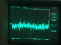
With a 2.20V pk-pk 40Hz sine wave entering into it the output RCAs put out a very fuzzy sine wave that fluctuates between 2.10 and 2.40 Volts.
With a 2.20V pk-pk 40Hz sine wave entering into it the output RCAs put out a very fuzzy sine wave that fluctuates between 2.10 and 2.40 Volts.
Did you ground the scope to the RCA output shield when viewing the signal.
That's not really important as long as the level is strong.
What's the DC voltage across terminals 1 and 2 of LCR1?
That's not really important as long as the level is strong.
What's the DC voltage across terminals 1 and 2 of LCR1?
I did, being mindful that the ground loop isolator prevents getting a decent ground in that side. I invested in some genuine Tektronix scope probes and measured the ground path resistance, all ok.
I measure 6.8V between 1&4.
I measure 6.8V between 1&4.
My apologies Perry, I had thought you meant the jack rather than the IC...😱
The amp is currently hooked up to the sub in the car, I’ll pull it out and open it up tomorrow.
Sorry for the mix up...
The amp is currently hooked up to the sub in the car, I’ll pull it out and open it up tomorrow.
Sorry for the mix up...
Did you ground the scope to the RCA output shield when viewing the signal.
That's not really important as long as the level is strong.
What's the DC voltage across terminals 1 and 2 of LCR1?
Finally had the time to pull the amp from the car.
The pins of LCR1 are inaccessible without taking the mosfets off the heatsink so I followed the schematic and hopefully correctly surmised I could take a measurement from the collector of Q10 for pin 1 and at R44 for pin 2.
Between these points I measured 9.97 Volts.
The RCA shield of the inputs measures 300kOhms+, the RCA shield of the auxiliary outputs measures a pretty stable 7 kOhms to ground.
There is an error in the service manual. I was looking at the pin configuration on the pin-out page. The diagram page has a different configuration. The LED that's given as 1-2 on the pin-out page goes from 12v to the transistor collector.
I see, so we want the voltage measurement across the LED portion of LCR1?
In that case measuring between the collector of Q10 to the 12v B+ terminal gives a voltage of around 3.3 ish volts. If I have understood correctly this is about what one would expect across the LED and so the LED is probably ok?
In that case measuring between the collector of Q10 to the 12v B+ terminal gives a voltage of around 3.3 ish volts. If I have understood correctly this is about what one would expect across the LED and so the LED is probably ok?
Last edited:
The LED looks OK. With the LED powered, the other two terminals should pass audio. Do you have the same level of audio on both of the other terminals?
I'm finding it difficult to get a clean reading on the oscilloscope, If I ground on the input RCA shield I get very fuzzy waveforms with about 150mV of negative offset, this is with driving 80Hz into the amp.
Measuring with the multi-meter set to AC gave 0.48V at R44 and 0.69 at C5. The measurement with the multi-meter was made at 50Hz as the multi-meter is the most accurate at this frequency.
Measuring with the multi-meter set to AC gave 0.48V at R44 and 0.69 at C5. The measurement with the multi-meter was made at 50Hz as the multi-meter is the most accurate at this frequency.
The first is the 'scope grounded to the RCA shield of the input side and the probe on the signal pin of the input side.
The second is the 'scope grounded to the RCA shield of the input side and the probe touched to the signal pin of the output side.
There is also infinite resistance between the RCA shields of the input side, that can't be right can it?😕
The second is the 'scope grounded to the RCA shield of the input side and the probe touched to the signal pin of the output side.
There is also infinite resistance between the RCA shields of the input side, that can't be right can it?😕
Attachments

Last edited:
That worked like magic, though I'm a bit baffled as to why?
For a voltage going in of 100mV P-P, I get 150 mV P-P out.
For a voltage going in of 100mV P-P, I get 150 mV P-P out.
Ground isn't the same everywhere, even if they are all directly connected (approximately 0 ohms between them). This is especially true for high frequencies.
Try bridging those two points to see if the level comes back up to where you expect it to be.
Try bridging those two points to see if the level comes back up to where you expect it to be.
- Home
- General Interest
- Car Audio
- Possible input issue on JBL GTO 1400.1