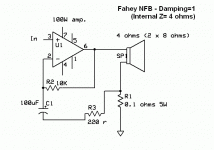
Many Thanks to all, but specifically to Marcel and KSTR for their schematics.
@ Marcel:
If I correctly understand your hand writing, the minus of the loudspeaker is directly connected with both R5, R6 and C3/4/5, all of which are then lifted from earth.
What is the function of the 100K R5 // to the R4+C3/4/5 network? I understand their combined function to set voltage gain in the voltage mode, but what about R5 in the modified arrangement?
No, with the Zobel to ground, the inductance of the loudspeaker causes an extra pole in the loop that probably makes it oscillate. You are right about the unplugged loudspeaker, but why do you care? With that 470 ohm shunt resistor, you much reduce the output impedance and make the current drive worse.
Why do i care? Because when voltage swings as high up and poor fellow plugs the speaker back, he and the speaker are up for a shock. Have you had full power to the speaker surprise you by accident? I did, its not fun. And you may need to replace tweeters.
Good luck.
Two more questions:
is the 470 Ohms resistor // lsp terminals there to stabilize/ballast the feedback loop in case the lsp is removed?
idem for the Zobel. Without it gain would substantially rise above say 1 Khz because of the increasing L value of the VC?
is the 470 Ohms resistor // lsp terminals there to stabilize/ballast the feedback loop in case the lsp is removed?
idem for the Zobel. Without it gain would substantially rise above say 1 Khz because of the increasing L value of the VC?
Yes, but with voltage drive it - generally -makes more sense to use a Zobel in a passive x/o than at the amp output. Isn't the whole purpose of voltage drive with a high damping factor to be relatively independent of lsp impedance?
BTW x/o sims&optimization show that even Zobel in a passive x/o does not always make sense. But let us not go there..
BTW x/o sims&optimization show that even Zobel in a passive x/o does not always make sense. But let us not go there..
Unfortunately, the low frequency resonant vibrations will remain largely undamped with this arrangement.
Unfortunately, the low frequency resonant vibrations will remain largely undamped with this arrangement.
Yes, but exactly that is what I want for my experiment.
Yes, but exactly that is what I want for my experiment.
And that is exactly what is so hard to accomplish. Conventional feedback does not understand slow changes.
@ Marcel:
If I correctly understand your hand writing, the minus of the loudspeaker is directly connected with both R5, R6 and C3/4/5, all of which are then lifted from earth.
Yes, that's what I have drawn.
What is the function of the 100K R5 // to the R4+C3/4/5 network? I understand their combined function to set voltage gain in the voltage mode, but what about R5 in the modified arrangement?
The purpose of R5 is to roughly compensate for the DC voltage drop across R3, the purpose of C3 + C4 + C5 is to filter off the noise of R5 and the purpose of R4 is to act as a base stopper for T2 and T4.
The feedback at high frequencies is set by R6 and the new resistor, assuming that the loudspeaker is inductive. That's why R6/new 0.47 ohm resistor = R5/R4. I hope that the frequency where the loop gain goes through 0 dB is higher than the corner frequency of C6 and R6 (about 159 kHz) because then the stability should stay essentially the same, but I haven't checked if that is true.
Why do i care? Because when voltage swings as high up and poor fellow plugs the speaker back, he and the speaker are up for a shock. Have you had full power to the speaker surprise you by accident? I did, its not fun. And you may need to replace tweeters.
Good luck.
I haven't, but it's not quite the same as a voltage amplifier running at full volume when you connect the loudspeaker. Ideally the voltage should jump straight back to normal values as soon as the loudspeaker closes the feedback loop, so you should only get a tick of a few microseconds.
Isn't the whole purpose of voltage drive with a high damping factor to be relatively independent of lsp impedance?
With voltage drive, the voltage is practically independent of the loudspeaker impedance but the current depends strongly on it, with current drive it is the other way around.
Similarly, with voltage drive, some of the not entirely linear effects in a loudspeaker cause distortion of the current, and with current drive, they cause distortion of the voltage.
Last edited:
Would it make sense to increase C6/R6 in value to lower the corner frequency of the combi substantially e.g. to halve it to say 80 kHz? I am well aware of the necessity to actually sim the amp to find that out, but as a "ball park" approach, would that work? The new 0.47 should then also be adapted to (re)set gain at 20. I am not sure with this amp unity gain would be above 159 kHz.
Nice guesses, but I have been making and selling high impedance output amplifiers for over 50 years now, currently over 14.000 of them, all used and abused on stage by those terrible users: Rock Musicians.
Don´t overthink it, imagine mystery ultrafrequency oscillations, etc.
To avoid redrawing, I´m posting the factor "1" damping amplifier, which I use for general purpose Guitar Players (Bass players too); for rabid Thrash Metal/Doom/Hardcore/etc. ones, who love chest thumping Bass and ear shredding chainsaw type mid/highs I go full current drive, by shorting the 220 ohm resistor (which provides a quota of voltage drive).
Amp gain then is simply speakerZ/0.22 ohm , whatever Z is.
Never cared to put a 470 ohm resistor in parallel with speakers, never had a problem, although now and thenamps are played unplugged by mistake or accient.
Zobel goes across speaker terminals and limits very high frequency gain, no influence at audio frequencies.
Don´t overthink it, it works. Battlefield proven and then some.
Ohm all resistors are wirewound.
Worrying about *tiny* inductance is irrelevant compared to intended load: a *speaker*.
In fact I make my own resistors out of 0.50mm Kanthal/Constantan wire, go figure.
Weird, I "attached" it.
Here it goes again:
Below some currently made amplifiers, using that 50 year old NFB system .
Shown at Buenos Aires AES convention, where I also lectured on "How to stand the Oriental Onslaught" being one of the very few manufacturers still working "since forever" , manufacturing everything locally (most of it on own premises) and outsourcing NOTHING, not even the PCBs.
Attachments
incomplete answer 😱 , should have added:I go full current drive, by shorting the 220 ohm resistor
"and replace 0.1 ohm sensing resistor by a 0.22 ohm one, to keep amp sensitivity constant"
Would it make sense to increase C6/R6 in value to lower the corner frequency of the combi substantially e.g. to halve it to say 80 kHz? I am well aware of the necessity to actually sim the amp to find that out, but as a "ball park" approach, would that work? The new 0.47 should then also be adapted to (re)set gain at 20. I am not sure with this amp unity gain would be above 159 kHz.
You could increase C6, but it is probably not needed. With the present value, it may give a bit of phase lead when the unity gain frequency is not that high, which will probably just improve stability. You can measure the small-signal square wave response and then the large-signal square wave response to find out if it is stable, just make sure you don't blow up any loudspeakers or more importantly ears.
Worrying about *tiny* inductance is irrelevant compared to intended load: a *speaker*.
That doesn't make any sense, or in your style, that doesn't make *any* sense.
The parasitic inductance of the 0.47 ohm or 0.1 ohm or 0.22 ohm or whatever resistor is in series with a very small resistance, so for a given inductance, the time constant L/R is relatively large. As it is the lower branch of the feedback network, it causes a zero at -R/L in the loop gain which could stabilize or destabilize the amplifier. If you want to make sure it doesn't do anything on stability, L/R must be << 1/(2 pi * frequency where the loop gain goes through 0 dB).
Frankly I haven't a clue what parasitic inductance a typical wirewound 0.47 ohm resistor has. It could be that it is already small enough, and besides, it could be that the zero actually improves stability, but in either case, that has no direct relation with the speaker impedance.
Last edited:
- Home
- Amplifiers
- Solid State
- Possible conversion into Current Amp?

