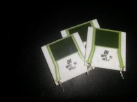
or maybe something like 3 of these in paralel:The extra 0.47 ohm resistor needs to have a power handling in the 5 to 10 W range and very little parasitic inductance, so I wouldn't use a wirewound type. You may have to use series and parallel connections of lower power resistors, or maybe one of these: . Audyn 0.47 Ohm 10 Watt MOX Besides, you may need to add an offset trimming circuit, like a potmeter between the positive and negative supplies with a 10 Mohm resistor from its wiper to R3.
Attachments
That doesn't make any sense, or in your style, that doesn't make *any* sense.....
Maybe not; *BUT* most guitar-amp companies use a plan *very* similar to Fahey's on their transistor amps (and especially large chip amps). Fender jumps to mind but also others; I am *no* longer startled when I *find* hi-Z output networks. (However Google is **NOT** cooperating tonight...)
Rod Elliott has a plan apparently unchanged since 2002, with values very much like Fahey's.
100W Guitar Amplifier (Mk II)
He does have a note about the physical location of the small-Ohm resistor which I did not read.
Attachments
My comment wasn't related to the use of mixed series and shunt feedback in guitar amplifiers, but to comparing the inductive reactance of the series feedback resistor with the loudspeaker impedance. I think it should be compared with the resistance of the series feedback resistor instead, which makes it 17...40 times more critical.
Still, I see that Elliott also uses wirewound resistors.
Still, I see that Elliott also uses wirewound resistors.
The coil in a 5W cement resistor is much smaller than a g-amp voice-coil. Of course the resistance is smaller also. In proportion? I do not know.
Here is a VERY "popular" product with a Fahey-like NFB (but elaborated like Mulrich was paid by the part), the Fender Frontman 212. I know it was widely sold because it comes up a lot on forums: the low-volt supply tends to bake itself crispy, the connectors tarnish, the beast is hard to dissect, etc.... but the NFB just works.
elektrotanya.com/fender_frontman_212r_sch.pdf/download.html
elektrotanya.com/fender_frontman_212r_sch.pdf/download.html#dl
{Hey! The #dl on Electrotanya bypasses the "I am Robot" trap!}
Attachments
It's a pity that wirewound resistor datasheets typically don't say anything at all about the parasitic inductance.
Don´t worry, inductance IS very low 🙂It's a pity that wirewound resistor datasheets typically don't say anything at all about the parasitic inductance.
And the speaker inductance is very much affecting the NFB loop.
I´d write very much 😀
Seriously, the NFB net controlling gain is made up of *two* components, period, the speaker and the current sensing resistor, and the speaker inductance is affecting the top branch of that voltage divider waaaayyyyy more than what self inductance affects the lower branch.
Measure it yourself 😎
Speakers are "pre-measured", just look at a published impedance curve:
Eminence Legend GB128, a typical 12" Guitar Speaker:
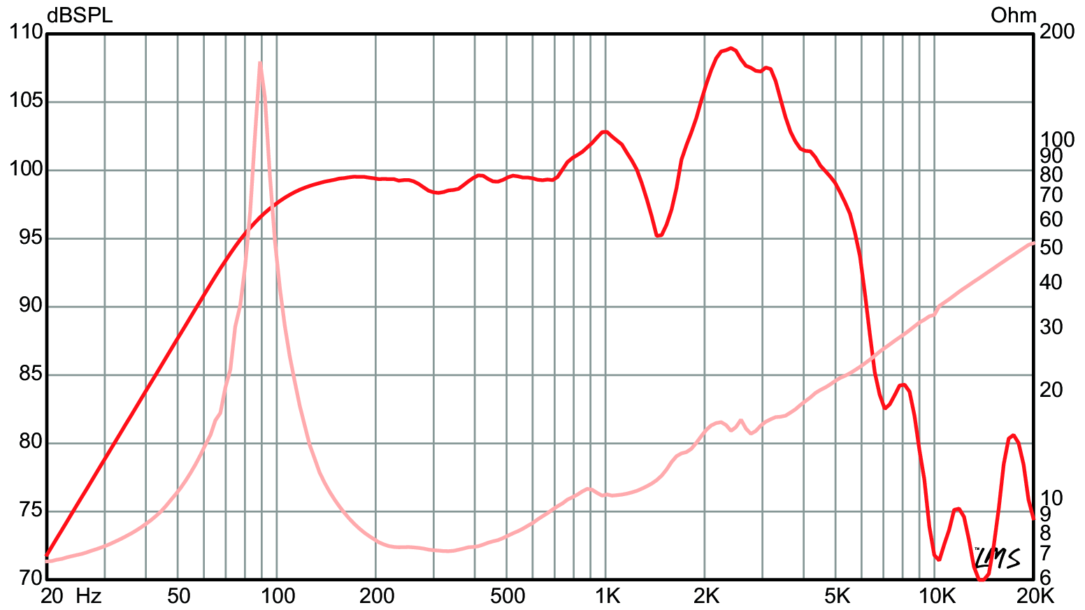
Notice that impedance *doubles* (16 ohm) at mere 2kHz 😱
And *sextuples* (48 ohm) at 20kHz

Do you think a plain commercial wirewound resistor doubles or sextuples impedance at such low frequencies?
Think again, or even better, measure it.
A very easy test setup, just feed it 2kHz and 20kHz through a , say, 10 ohm resistor and measure voltage drop across the wirewound one, compared to, say, voltage drop at 100 or 200 Hz.
Again, the amplifier is not merely driving the speaker (which already loads and influences it) but its gain comes straight from speaker wildly varying impedance, which includes a strong inductive component.
It is my understanding that with increasing Z, power goes up considerably with current drive. At resonance power to the speaker may well be 5 times or more the power delivered at say 200 Hz because of the Z peak at resonance. So yes, the gain is related to the wildly varying impedance. No discussion there.
But what we see here in the Eminence measurement looks like classic voltage drive.
But what we see here in the Eminence measurement looks like classic voltage drive.
Don´t worry, inductance IS very low 🙂
And the speaker inductance is very much affecting the NFB loop.
I´d write very much 😀
Seriously, the NFB net controlling gain is made up of *two* components, period, the speaker and the current sensing resistor, and the speaker inductance is affecting the top branch of that voltage divider waaaayyyyy more than what self inductance affects the lower branch.
Measure it yourself 😎
Speakers are "pre-measured", just look at a published impedance curve:
Eminence Legend GB128, a typical 12" Guitar Speaker:
Notice that impedance *doubles* (16 ohm) at mere 2kHz 😱
And *sextuples* (48 ohm) at 20kHz
Do you think a plain commercial wirewound resistor doubles or sextuples impedance at such low frequencies?
Think again, or even better, measure it.
A very easy test setup, just feed it 2kHz and 20kHz through a , say, 10 ohm resistor and measure voltage drop across the wirewound one, compared to, say, voltage drop at 100 or 200 Hz.
Again, the amplifier is not merely driving the speaker (which already loads and influences it) but its gain comes straight from speaker wildly varying impedance, which includes a strong inductive component.
You are right, of course, but that's why I suggested connecting the Zobel network in parallel with the speaker (or speaker + L1//R7 actually). You suggested that as well, so at least we agree on that part.
I'm mainly concerned about the stability of the feedback loop, so about what happens where the magnitude of the loop gain goes through 0 dB. According to a rather idealized calculation, that's around 700 kHz, so at those frequencies, the loudspeaker is essentially an open branch and the Zobel resistor R6 and the current sensing resistor form the feedback network, rather than the loudspeaker and the current sensing resistor.
When the L/R time constant of the current sensing resistor is less than 50 nanoseconds or so, it probably won't affect stability significantly. If it is in the 100 ns to 200 ns range, the phase lead may improve stability, if you are lucky. If it is much higher, anything can happen. 50 ns and 0.47 ohm means 23.5 nH, roughly the inductance of an inch of straight wire. 200 ns and 0.47 ohm means 94 nH, roughly the inductance of 10 cm of straight wire.
I've never done the experiment, but what kind of L/R time constants have you measured for wirewound resistors in the 0.1 ohm to 0.47 ohm ballpark?
Last edited:
It is my understanding that with increasing Z, power goes up considerably with current drive. At resonance power to the speaker may well be 5 times or more the power delivered at say 200 Hz because of the Z peak at resonance. So yes, the gain is related to the wildly varying impedance. No discussion there.
But what we see here in the Eminence measurement looks like classic voltage drive.
I think JMFahey just wanted to show the impedance curve, but the SPL plot under voltage drive happened to be in the same picture. For current drive, just add 20 dB*log10(mag(Z)) to the SPL plot under voltage drive.
Only measured within the Audio range, so not higher than 20kHz, and withinh that range resistors were basically resistive, essentially constant impedance.I've never done the experiment, but what kind of L/R time constants have you measured for wirewound resistors in the 0.1 ohm to 0.47 ohm ballpark?
Never measured at 100´s of kHz but my indirect verification is that I never had oscillations.
Not sure it applies to Hi Fi amps where you strive for *extended* frequency response hoping for perfect response within the audible band, mine are intended as workhorses and really don´t need much above, say, 10 kHz.
What the best way?
Hi all and Mr JMFahey: there are indications about using or not the capacitor C1, of your scheme. Without the C1, they say a pure current amplifier remains. But there is a big offset imbalance, which doesn't work when you have the electrolytic C1. After all, what is the best system? Thank you.
Weird, I "attached" it.
Here it goes again:
Below some currently made amplifiers, using that 50 year old NFB system .
Shown at Buenos Aires AES convention, where I also lectured on "How to stand the Oriental Onslaught" being one of the very few manufacturers still working "since forever" , manufacturing everything locally (most of it on own premises) and outsourcing NOTHING, not even the PCBs.
Hi all and Mr JMFahey: there are indications about using or not the capacitor C1, of your scheme. Without the C1, they say a pure current amplifier remains. But there is a big offset imbalance, which doesn't work when you have the electrolytic C1. After all, what is the best system? Thank you.
Only measured within the Audio range, so not higher than 20kHz, and withinh that range resistors were basically resistive, essentially constant impedance.
Never measured at 100´s of kHz but my indirect verification is that I never had oscillations.
Not sure it applies to Hi Fi amps where you strive for *extended* frequency response hoping for perfect response within the audible band, mine are intended as workhorses and really don´t need much above, say, 10 kHz.
I can see that, and that the inverting input sums the sensing resistor current across that which consists of electrons flowing from earth. This is like tapping into a water hydrant to control a fire - in more than a figurative sense.
Impedance increases with power. There is a need for a sensing mechanism for cone position, an accelerometer or something. An unlikely successful implementation would result in considerably reduced efficiency.
NFB makes the "large Op Amp" which Linn configuration amplifiers are, *behave* as a current source.Hi all and Mr JMFahey: there are indications about using or not the capacitor C1, of your scheme. Without the C1, they say a pure current amplifier remains. But there is a big offset imbalance, which doesn't work when you have the electrolytic C1. After all, what is the best system? Thank you.
C1 is chosen large enough that at Audio frequencies it remains "invisible" so response is the same with or without it but it has the useful property of making DC gain = 1 so minimizing offset.
With not particular care my amps show offset in the 15mV to 45mV range tops; if I in some cases I find it important, such as when I add a 4/8/16 ohm autotransformer at the output of Guitar amp heads to match "what a Marshall tube amp offers" I can easily match input transistors to get 5mV or less since OT DCR can be as low as 0.2 ohm
It´s even simpler than that, the Power Amp is nothing but "a large Op Amp" and behaves as that.the inverting input sums the sensing resistor current across that which consists of electrons flowing from earth.
It is always a voltage controlled amplifier , obeys what NFB tells it, only that the *voltage* it´s following happens to be that dropped across the grounded sensing resistor, which happens to be I*R .
Since R is constant, Power amp output voltage will follow current through the load, so it will behave like a current source.
That´s the beauty of Op Amps, you can imitate whatever you want, within the Analog realm.
When I started studying Engineering in 1969, simultaneously with building my first amplifiers, Op Amps were the new solve-it-all technology which I embraced with passion, simultaneously hating anything Digital, to this day.
Hello everyone and dear Mr JMfahey: thank you very much for the explanation, useful for me. I love current amplifiers, I have audio in my home with electronic Xover and each speaker answers his amplifier. Works great with current amp. Greetings.
- Home
- Amplifiers
- Solid State
- Possible conversion into Current Amp?