I have a single ended Tube amp I've been working on. I looking at a sine wave or the output transformer and it looks asymmetrical to me. The positive side of sine wave seems elongated. Attached is shot from the scope. the yellow line is the output measured across an 8ohm resistor connected to the speaker outputs. The green is the signal from the input tube, measured at the coupling capacitor where it goes to the output tube grid. I've tied to scale the two to make a good comparison, It looks to me like the input tube looks pretty even. But something wonky with the output. I looked at another amp I have it looks more even. So what does this tell me? What may be causing this? (note that using an Oscope is new to me so I'm not sure exactly what to take away from what I'm seeing)
Attachments
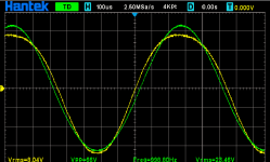
The yellow trace is the output, correct? It looks like that's about 8Vrms. What load is that running into? If 8 ohms that would be 8Wrms output, which is probably as much power as the amp can put out. If so, you're looking at the distortion the amp is making.
Even harmonics will make one half of the waveform look different than the other half of the waveform. Odd harmonics will look symmetrical. You say this is a single-ended amplifier? That would make sense. It looks like the amp is making a lot of even order harmonics.
Is that other amp you have that makes a more even looking output waveform a push-pull amplifier?
You are experiencing 2nd harmonic distortion.
A single ended amplifier normally has dominant 2nd harmonic distortion.
You did not say if you used a triode, pentode, or beam power output tube.
And you did not say if the pentode / beam power tube was wired for pentode / beam power mode, Ultra Linear mode, or Triode wired mode.
Look at a set of triode plate curves.
At high negative grid voltage, high plate voltage, and low plate current, the plate curves are bent/rounded.
At the low negative grid voltage, low plate voltage, high plate current, the plate curves are straight.
If you draw a load line equal to your output transformer primary impedance, through the plate curves, you will see that a change of grid voltage at the right side of the graph, there is less plate voltage change; and that an equal change of grid voltage at the left side of the graph, there is more plate voltage change.
More plate voltage change = a larger 1/2 of the sine wave.
Less plate voltage change = a smaller 1/2 of the sine wave.
You will also notice that the negative alternation below zero volts is 4.6 time units wide ("narrow"), and the positive alternation above zero volts is 5.4 time units wide ("fat"). Just as we expect for that amount of 2nd harmonic distortion of a single ended output stage.
The positive is 'foreshortened', the negative is 'lengthened'.
Would you please post a schematic of your single ended amplifier.
Last edited:
Yes, yellow is the output. and at 8volts it is just before it goes into a more obvious clip. But at 4 volts or its similar. The amp I compared to is also single ended and uses same type of tubes and at about 8 volts right before clipping more symmetrical.
No negative feedback on either.Or is the other amplifier one with negative feedback, while this one has none?
Thanks, I sort of got that it was product of the Harmonic distortion. I guess I'm really wondering to what degree is it normal and what can be done to minimize the difference (or do i even need to?). Here's the schematic. Started from the Mikael Abdellah amp, and made adjustments for using 5881 tube.You are experiencing 2nd harmonic distortion.
A single ended amplifier normally has dominant 2nd harmonic distortion.
You did not say if you used a triode, pentode, or beam power output tube.
And you did not say if the pentode / beam power tube was wired for pentode / beam power mode, Ultra Linear mode, or Triode wired mode.
Look at a set of triode plate curves.
At high negative grid voltage, high plate voltage, and low plate current, the plate curves are bent/rounded.
At the low negative grid voltage, low plate voltage, high plate current, the plate curves are straight.
If you draw a load line equal to your output transformer primary impedance, through the plate curves, you will see that a change of grid voltage at the right side of the graph, there is less plate voltage change; and that an equal change of grid voltage at the left side of the graph, there is more plate voltage change.
More plate voltage change = a larger 1/2 of the sine wave.
Less plate voltage change = a smaller 1/2 of the sine wave.
Would you post a schematic of your single ended amplifier, please.
Attachments

The gain of all active devices falls to zero at zero current.
As your tube plate swings one way, low current flattens the wave; the other way, high current elongates the wave. ALL simple amplifiers do this.
This really does not sound as bad as it looks!
NFB will reduce the difference, if it can, if not too extreme.
Push-pull can fill-in the low-gain flats and maybe reduce the elongation.
There are a fair number of audio situations where a pinch or a shovel-full of 2nd harmonics sweetens the dish.
No negative feedback . . .
On the amplifier that has less 2nd harmonic distorton, there may be cancellation from the driver stage 2nd harmonic (of one phase), with the output stage 2nd harmonic (of the opposite phase).
Or, the quiescent operating conditions of one output tube, may be different than the quiescent operating conditions of the other amplifiers same kind of output tube . . .
Plate voltage, plate current, output transformer primary impedance, etc.
Schematics?
Voltages?
Resistances?
Or, perhaps one 'identical tube' is kind of soft or wimpy, versus the other tube.
Are both amplifiers identical schematics and parts?
Vp-k 390V - 31V = 359V
31V / 500 Ohms = 0.062A (62mA)
359V x 0.062A = 22.26 Watts plate (and screen) dissipation
Screen, Vs-k ~ 359V
5881
Vp 360V maximum, some later data sheets higher voltage rating than this.
Wp 23 Watts maximum beam power mode, Wp+s 26 Watts triode wired mode.
Screen, 270V maximum, some later data sheets higher voltage rating than this.
It looks like you would be running older / original 5881 tubes pretty close to, or beyond the original ratings.
If you swap the two 5881 tubes you have, does the distortion follow the tube?
A 40% screen tap, with 395V B+ and 390V plate, would put the screen tap at about 393V. Subtract 31V cathode bias from that, and whatever drop there is in the 1.8k screen resistor, that is the screen to cathode volts.
Chances are, the screen volts may be higher than the plate volts (In UL, that is often the case).
For a strong 5881, try the JJ 5881.
I just drive over to eurotubes.com, in the US, and I pick up my JJ tubes. They all get re-tested after they come from JJ in Slovakia.
Last edited:
Looks basically the same on both channels newer 5881, also with 6l6gc, 6ca7, kt88, 6550sAre both amplifiers identical schematics and parts?
Vp-k 390V - 31V = 359V
31V / 500 Ohms = 0.062A (62mA)
359V x 0.062A = 22.26 Watts plate (and screen) dissipation
Screen, Vs-k ~ 359V
5881
Vp 360V maximum, some later data sheets higher voltage rating than this.
Wp 23 Watts maximum beam power mode, Wp+s 26 Watts triode wired mode.
Screen, 270V maximum, some later data sheets higher voltage rating than this.
It looks like you would be running older / original 5881 tubes pretty close to, or beyond the original ratings.
If you swap the 5881 tubes, does the distortion follow the tube?
Do both driver tubes look identically linear?
Or is one driver tube distorting (2nd harmonic), and cancelling the output stage distortion (2nd harmonic)?
Are both output transformer primaries the same?
A swap of plate lead and screen lead would make that amplifier have more 2nd harmonic distortion.
You need to measure 100V plate, 40V screen tap signal, if the UL tap is rated for 40%.
Manufacturers have been known to swap the colors from one transformer to the other transformer.
Or, there must be some other difference between the parts.
Last edited:
The amp I used as comparison is a Tubelab SSE, its driver looks linear too. I originally saw that the tube labs output as just an indication that a more symmetrical (linear) output could be expected, or obtained. There are differences, notably the SSE uses a CCS on the plate of the driver, The B+ is higher, I need to go back and check just to see how much and compare the operating points. And the OPT is 5k vs 3.5k for the amp i'm looking at now, both edcor gxe 15w . And maybe its just that. I think the point I picked is good for the power xformer and OPT I have, and maybe if I moved the loadline up or had a different slope (5k vs 3.5k) I would be in a more linear section. I'm going to take some measurements on the SSE again, and look at the UL taps. I think the amp sounds good, but I recently got the oscope, so it's got me looking at things and asking why.Do both driver tubes look identically linear?
Or is one driver tube distorting (2nd harmonic), and cancelling the output stage distortion (2nd harmonic)?
Are both output transformer primaries the same?
A swap of plate lead and screen lead would make that amplifier have more 2nd harmonic distortion.
You need to measure 100V plate, 40V screen tap signal, if the UL tap is rated for 40%.
Manufacturers have been known to swap the colors from one transformer to the other transformer.
Or, there must be some other difference between the parts.
So what we see on the scope , 8Vrms in to 8 ohm load which is 8W ?
At what lower power you can't see distortion on the scope ?
At what lower power you can't see distortion on the scope ?
Take the amplifier with the 3.5k output transformer, then set it for 5.6Vrms, 1kHz sine wave on the 8 Ohm tap with an 8 Ohm load, and then remove the sign wave, re-connect the 8 Ohm load to the 4 Ohm tap (if there is one), turn the sign wave on again, and look to see if the sine wave is shaped differently.
Try that again, with the sine wave set to 8Vrms.
Take the amplifier with the 5k output transformer, then set it for 5.6Vrms, 1kHz sine wave on the 8 Ohm tap with an 8 Ohm load, and then remove the sign wave, re-connect the 8 Ohm load to the 16 Ohm tap (if there is one), turn the sign wave on again, and look to see if the sine wave is shaped differently.
Try that again, with the sine wave set to 8Vrms.
This should tell you something about how the impedance of the plate load changes the 2nd harmonic distortion.
Just Saying . . .
Try that again, with the sine wave set to 8Vrms.
Take the amplifier with the 5k output transformer, then set it for 5.6Vrms, 1kHz sine wave on the 8 Ohm tap with an 8 Ohm load, and then remove the sign wave, re-connect the 8 Ohm load to the 16 Ohm tap (if there is one), turn the sign wave on again, and look to see if the sine wave is shaped differently.
Try that again, with the sine wave set to 8Vrms.
This should tell you something about how the impedance of the plate load changes the 2nd harmonic distortion.
Just Saying . . .
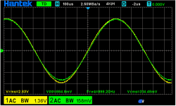
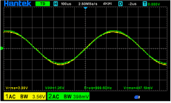
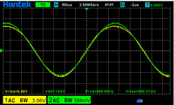
I took some shots, this time the green line is after the volume pot before input tube. Yellow is the output. And it does seem like they match pretty well then the top starts dropping and streaching after 6v. 4.5 w not an unexpected value I guess. I'm just wonder what is normal to expect. Maybe nothing wrong here at all.So what we see on the scope , 8Vrms in to 8 ohm load which is 8W ?
At what lower power you can't see distortion on the scope ?
Attachments
This sounds like a good exercise. Unfortunately, they both only have 8 ohm taps. I may have to buy some new transformers just to try this out. Thanks. So i take it that what i'm seeing is the expected outcome given the 3.5k transformer, giving me a less linear loadline than the 5k would?Take the amplifier with the 3.5k output transformer, then set it for 5.6Vrms, 1kHz sine wave on the 8 Ohm tap with an 8 Ohm load, and then remove the sign wave, re-connect the 8 Ohm load to the 4 Ohm tap (if there is one), turn the sign wave on again, and look to see if the sine wave is shaped differently.
Try that again, with the sine wave set to 8Vrms.
Take the amplifier with the 5k output transformer, then set it for 5.6Vrms, 1kHz sine wave on the 8 Ohm tap with an 8 Ohm load, and then remove the sign wave, re-connect the 8 Ohm load to the 16 Ohm tap (if there is one), turn the sign wave on again, and look to see if the sine wave is shaped differently.
Try that again, with the sine wave set to 8Vrms.
This should tell you something about how the impedance of the plate load changes the 2nd harmonic distortion.
Just Saying . . .
It is not that bad without negative feedback , probably the tube in those operating conditions requires slightly different Ra load than 3K5 . Probably higher .
Hard to say because is ultralinear .
Anyway it is perfectly normal to have some 2nd harmonic distortion at high power output . This is what you see on the scope .
Hard to say because is ultralinear .
Anyway it is perfectly normal to have some 2nd harmonic distortion at high power output . This is what you see on the scope .
Last edited:
Power tube driving (grid) signal voltage would show more.green line is after the volume pot before input tube. Yellow is the output.
1.) Debugging only one stage: output waveform, driving waveform.
If it (examined waveform) also distorted, go back one stage, and GO TO 1. 😛
- Home
- Amplifiers
- Tubes / Valves
- Positive side of sine wave seems elongated