But the imbalance is cleared?
Not yet Osvaldo, I pulled the board from heatsink and gave it a good clean underneath.
There is nothing obvious so I am hoping that replacing the capacitor will cure the problem.
OK, while waiting for the new caps, you can make a first test, interchanging both capacitors, and see if the fault persist in the same cap or in the same bus. There exists some percentage of probabilities that the cap be not guilty.
🙂 A trick from a "repairman" more than an Engineer.Warning not to broke the through holes, if metalized. Exhaust well all the solder previous to extract the caps.That’s a great idea
Is it diagnostically relevant that the output transistors on the left side are running much warmer at idle than than the right?
Last edited:
Yeah! An overheating reveals a problem, an overbiased amp or directly faulty, causing overloading in the PSU. A good point to examine.
Ok so I measure:
-10.2v at the base of Q112, (left channel)
-11.4v at the base of Q113, (left channel)
+0.5v at the base of Q212 (right channel)
-0.5v at the base of Q213 (right channel)
Ground referenced to the secondary side, no signal.
Should be +- 0.5 on both sides according to the schematic.
No wonder it was running hot...😱
Last edited:
Definitively something is wrong in lest channel. Measurements cold of resistances and transistor is what I may suggest.
Previous to it discharge all caps with a 100Ω resistor and wait them to rebuild some charge, and re-discharge, mainly the buses caps, several times. ('lytic caps rebuild some charge after a full discharge, so discharge them until no further build up you found). Unproper cap discharge will cause erroneous resistance measurements including negative ohms‼
Previous to it discharge all caps with a 100Ω resistor and wait them to rebuild some charge, and re-discharge, mainly the buses caps, several times. ('lytic caps rebuild some charge after a full discharge, so discharge them until no further build up you found). Unproper cap discharge will cause erroneous resistance measurements including negative ohms‼
When the amp is cold the voltages across Q112&Q113 are much lower, around 4v and then climb as it gets hotter.
I'm not sure I understand what might cause that, especially as this amp doesn't have any means that I can see of setting bias?
I'm not sure I understand what might cause that, especially as this amp doesn't have any means that I can see of setting bias?
Bias are fixed by D103 and D104, so no chance to modify it without severe handling of the amps.
Which voltages increases, VBE or VCE?
Which voltages increases, VBE or VCE?
Sorry, I'm a bit dizzy. Four volts across bases? Its largelly excessive. There must be 2VΓ, about 1.2≈1.5V.
Yes, four volts across the bases whereas in post 49 they were around 10v.
I have swapped the capacitors and it has not corrected the issue.
I think i need to be more systematic about this.
I have swapped the capacitors and it has not corrected the issue.
I think i need to be more systematic about this.
Check Q108, Q109, Q110, D104, D105 and the resistors associated. Something is bad. Very bad :-(.
Testing them with the diode check seems to indicate that they are ok, will I have to remove them from the circuit and test with one of those transistor testers?
Not necessarily, usually a simple diode and transistor check with the diode drop from any DMM will tell U if there is any damaged part.
A quick update,
I removed Q901 and tested it as the voltages on Q101 and Q202 were all wrong ( should have been 0.7 volts on the Bases and 0 on the Emitters and Collectors, whereas they were in fact: Q101 - E:7.45v ; C:7.45v ; B:8.16v and Q202 - E:8.65v ; C:8.65v ; B:8.65v).
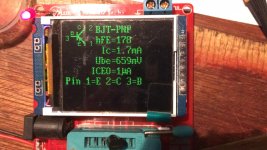
I obtained one of those transistor boards with the ZIF socket and obtained the attached results.
This transistor is a 2SA733-k and the values given below seem a little off.
the measured Hfe seems a little low for a k variant but is above the minimum given for a general 2SA733.
The Ic seems well out, the data sheet gives it as not more than 100nA whereas the device seems to measure 1.7 mA.
Is this transistor bad?
Datasheet: https://www.mouser.com/datasheet/2/149/2SA733-310191.pdf
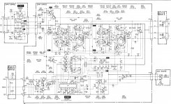
Schematic given below, transistors in question towards the top left of the diagram
I removed Q901 and tested it as the voltages on Q101 and Q202 were all wrong ( should have been 0.7 volts on the Bases and 0 on the Emitters and Collectors, whereas they were in fact: Q101 - E:7.45v ; C:7.45v ; B:8.16v and Q202 - E:8.65v ; C:8.65v ; B:8.65v).
I obtained one of those transistor boards with the ZIF socket and obtained the attached results.
This transistor is a 2SA733-k and the values given below seem a little off.
the measured Hfe seems a little low for a k variant but is above the minimum given for a general 2SA733.
The Ic seems well out, the data sheet gives it as not more than 100nA whereas the device seems to measure 1.7 mA.
Is this transistor bad?
Datasheet: https://www.mouser.com/datasheet/2/149/2SA733-310191.pdf
Schematic given below, transistors in question towards the top left of the diagram
Attachments
Last edited:
No. the transistor gives you the current you program in the circuit, givenm certain base and emitter resistors and other parameters. The data sheet usually gives you a certain point of quisient operation to give you an idea of its capabilities.
Think a transistor like water valve. Given certain aperture, altitude of liquid and pipe diameter, it will give you certain amount of water per second.
The Hfe is the most important parameter in a BJT, but in the manufacturing process is impossible to predict the value of it, so they are characterized into ranges, like resistors. So you will have, say, 100-250 200-500 and 450-800 for example. And apply some code to identify it. Hfe also varies largely with temperature.
- Home
- General Interest
- Car Audio
- Positive power supply rail at a different potential than negative rail?