I was thinking a lot how to design fullrange "box" (better said closed volume) , that will allow quick & simple installation, and that will be based on cheap material.
So, I designed this "box" from three major parts:
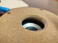
a) First part is flange driver adapter , made from plywood.
It has conically shaped hole in the center , that will enable smooth transition from 2.5" driver to horn mouth, but it also has one 5mm x 5mm groove cut, for seal foam.
b) Second part is 70mm PVC pipe , cut to 50mm length, with end cap pressed to close it from one side.
Important thing is that I used part of PVC pipe that has enlarged one end, that will seal against flange adapter groove.
c) Third part is simple 4-bolt "clamp" , machined from plywood.
This clamp will attach to 70mm pipe, and will compress it against foam seal on flange adapter.


So now - the moment of truth - first assembly.😎
I am aware that I left very small tolerances in my design, but during assembly, it is scary how tight are some of them.
But before assembly, just one size comparison of new 100mm flanged bass reflex port compared to my 18V battery drill :


So, I designed this "box" from three major parts:
a) First part is flange driver adapter , made from plywood.
It has conically shaped hole in the center , that will enable smooth transition from 2.5" driver to horn mouth, but it also has one 5mm x 5mm groove cut, for seal foam.
b) Second part is 70mm PVC pipe , cut to 50mm length, with end cap pressed to close it from one side.
Important thing is that I used part of PVC pipe that has enlarged one end, that will seal against flange adapter groove.
c) Third part is simple 4-bolt "clamp" , machined from plywood.
This clamp will attach to 70mm pipe, and will compress it against foam seal on flange adapter.
So now - the moment of truth - first assembly.😎
I am aware that I left very small tolerances in my design, but during assembly, it is scary how tight are some of them.
But before assembly, just one size comparison of new 100mm flanged bass reflex port compared to my 18V battery drill :
Attachments


Love it.
Amazing builds🔥
Mobile raves whereever you require them🙂
Will be really interesting to hear what you think of them / how they measure.
Was it impossible to have the reflex ports in the fore area of the horn mouth ala Danley?
MEH are amazing!
Amazing builds🔥
Mobile raves whereever you require them🙂
Will be really interesting to hear what you think of them / how they measure.
Was it impossible to have the reflex ports in the fore area of the horn mouth ala Danley?
MEH are amazing!
2 Speedysteve7:
Thanks, I am trying my best 🙂
Yes, the idea is to take speaker wherever you want, and to still have not only decent output, but excellent coverage, with clear , coherent sound.
Don't worry, as soon as I assemble them, I will write down my subjective opinion and measurements as well.😉
Regarding bass reflex ports in horn mouth:
- Yes, I am aware of such port placement, but discarded this option for two reasons:
a) First and most important is to minimize influence of additional holes on horn surface.
Each hole on horn cause issues in acoustic response, so even though holes could be placed on edge
of the horn mouth where their influence is probably lest critical , it would still probably cause some issues that have to be sorted by DSP.
To maximize surface area (to reduce port chuffing) I would have to drill at least 4 large holes in each horn mouth, and I already have 4 large woofer injection ports.
b) Second reason is that with my design (two horns in one box, placed at 90 degree angle), there will be large empty space between two horn mouth, which can't be avoided => if I want to move horn closer to each other, then full range drivers will touch each other.
So to make some use of this large surface between two horn mouths (approx 300 x 350mm), I decided to install largest bass reflex ports that could fit, to minimize port chuffing.
While waiting for missing parts, I decided to quickly assemble speaker with existing components, scavenged from my single MEH bluetooth prototype.
Therefore, I took following items:
Such setup will not be able to produce maximum volume as with two 3255 amp boards , powered by 42 V DC total, but at least I can start with DSP adjustments, and I can at least enjoy in music finally 🙂
To mount all above electronics, I designed removable cover , and cut it on CNC from 6mm HPL laminate left overs - this material cuts nicely, and is very dense & strong, so it should resist vibrations:


As this is temporary panel, I've played with single line fonts for engraving just for fun:

Speaker wiring was connected and panel was tightened with allen bolts (lot of them, as you can see), and then speaker was powered on.
Couple of quick REW measurements later (in indoor conditions, not ideal) and couple of things were noted:
a) Small 5W fullranger simply can't keep with woofer output, which was of course expected => while it sounds quite clear and natural, when pushed to maximum power it just can't provide sufficient output in mids, and especially in higher freq range.
I am just affraid that I will burn fragile 5W coil with max power, even though I have crossover at 600Hz, but this cheap fullranger doesn't sound disstressed, at least now.
b) Woofers have plenty of output, and with shorter bass reflex tubes (130mm) , speaker has slightly raised low frequency response.
I can't believe that I am saying that, but I have too much bass in the moment => I believe that with SB Acoustics 2.5" fullranger, mid/high range will raise and it will get to desired level.
c) On maximum power , the box is quite inert, even though I was affraid that 9mm ply will not be sufficeintly strong, so it is not producing any funny noises.
d) Bass reflex ports are definitely not an overkill => the amount of air volume is quite high, and it will be even higher with new amps, so I am satisfied with my choice.
How do they sound ?
Extremely clean - even with this tiny, cheap 2" fullrange speaker, which I removed from old PC speaker, everything sounds very, very clear.
The typical MEH sound, is here, but because of two horns mounted on angle, the coverage is definitely wider, but I have to do measurements outdoor to see real benefits & drawbacks.
There is more than enough bass, and it goes sufficiently deep for the purpose - I've tested only indoor for now, and they can easily go to 50Hz with short bass reflex ports, and without any extra bass compensation in DSP.
Here is short video, recorded indoors:
Therefore, I took following items:
- "Arylic" Up2Stream 2.1 plate amp,
- Single battery board (21V DC),
- Two old fullrange, no-name drivers (5 W each).
- Additional DC/DC converter board (to raise voltage to 24V DC - maximum for "Arylic" amp).
Such setup will not be able to produce maximum volume as with two 3255 amp boards , powered by 42 V DC total, but at least I can start with DSP adjustments, and I can at least enjoy in music finally 🙂
To mount all above electronics, I designed removable cover , and cut it on CNC from 6mm HPL laminate left overs - this material cuts nicely, and is very dense & strong, so it should resist vibrations:
As this is temporary panel, I've played with single line fonts for engraving just for fun:
Speaker wiring was connected and panel was tightened with allen bolts (lot of them, as you can see), and then speaker was powered on.
Couple of quick REW measurements later (in indoor conditions, not ideal) and couple of things were noted:
a) Small 5W fullranger simply can't keep with woofer output, which was of course expected => while it sounds quite clear and natural, when pushed to maximum power it just can't provide sufficient output in mids, and especially in higher freq range.
I am just affraid that I will burn fragile 5W coil with max power, even though I have crossover at 600Hz, but this cheap fullranger doesn't sound disstressed, at least now.
b) Woofers have plenty of output, and with shorter bass reflex tubes (130mm) , speaker has slightly raised low frequency response.
I can't believe that I am saying that, but I have too much bass in the moment => I believe that with SB Acoustics 2.5" fullranger, mid/high range will raise and it will get to desired level.
c) On maximum power , the box is quite inert, even though I was affraid that 9mm ply will not be sufficeintly strong, so it is not producing any funny noises.
d) Bass reflex ports are definitely not an overkill => the amount of air volume is quite high, and it will be even higher with new amps, so I am satisfied with my choice.
How do they sound ?
Extremely clean - even with this tiny, cheap 2" fullrange speaker, which I removed from old PC speaker, everything sounds very, very clear.
The typical MEH sound, is here, but because of two horns mounted on angle, the coverage is definitely wider, but I have to do measurements outdoor to see real benefits & drawbacks.
There is more than enough bass, and it goes sufficiently deep for the purpose - I've tested only indoor for now, and they can easily go to 50Hz with short bass reflex ports, and without any extra bass compensation in DSP.
Here is short video, recorded indoors:
Last edited:
OK, so in last two months many interesting things happened, so just to summarize them in couple of sentences:
1.) Finally, "SB Acoustics" 2.5" fullrange driver arrived somewhere in December 2024, together with two stereo TPA3255 boards with DSP => but I couldn't use new amp boards due serious flaw in amp board design (I will explain later, quite funny story actually 😛).
2.) Then, new 6000mAh battery cells (26650 type ) finally arrived in January 2025 => but of course I can't use them together with my old battery board to get 42V DC supply , as new TPA3255 amp boards were useless for my application.🙄
3.) Nevertheless, I used exiting "Arylic" 2.1 plate amp to temporarily power the speaker, and performed some measurements with REW.
4.) What is maybe most important, I used speaker for its first party event successfully =>I was satisfied with its performance, though of course. there is always room for improvement🙂
So let's go with some pics of "SB Acoustics" fullranger installation & some other mods.
Here is box full of goodies , SB Acoustics fullrange drivers, new TPA 3255 boards with DSP, cable sets, additional battery board, etc.:


This driver looks quite well built:

I've added sealing tape around both drivers:

Here is comparison between "SB Acoustics" 2.5" driver and my no-name, 6W driver that I temporarily used:

Driver attached to plywood flange adapter:

One of the last feature that I wanted to add on my box is standard PA loudspeaker stand adapter (35mm diameter).
To add this, I knew from my 3D model that it will be a tight fit due lower bass reflex pipe (100mm dia) => so, I decided to use short 35mm adapter, but it also require additional shortening as you can see from pic below (grinder & TIG welder, my favorite tools).

As this 35mm flange adapter has to be mounted ideally at Center of Gravity point (CG), I used following method:
a) I've attached everything inside speaker (all drivers, amp boards, battery board, panels, etc.) ,to get to final weight,
b) Then I taped lower bottom area of the speaker with masking tape => specifically around center line as I know that flange will be placed somewhere along this line,
c) After that, I placed 35mm flange adapter on solid surface, with support, so it stays steady,
d) Then I placed carefully speaker on the flange adapter and I slide it along the line until I found most stable position, where the speaker balance was optimum.
e) This position was then marked on masking tape, so I know where to drill the holes for mounting flange adapter


1.) Finally, "SB Acoustics" 2.5" fullrange driver arrived somewhere in December 2024, together with two stereo TPA3255 boards with DSP => but I couldn't use new amp boards due serious flaw in amp board design (I will explain later, quite funny story actually 😛).
2.) Then, new 6000mAh battery cells (26650 type ) finally arrived in January 2025 => but of course I can't use them together with my old battery board to get 42V DC supply , as new TPA3255 amp boards were useless for my application.🙄
3.) Nevertheless, I used exiting "Arylic" 2.1 plate amp to temporarily power the speaker, and performed some measurements with REW.
4.) What is maybe most important, I used speaker for its first party event successfully =>I was satisfied with its performance, though of course. there is always room for improvement🙂
So let's go with some pics of "SB Acoustics" fullranger installation & some other mods.
Here is box full of goodies , SB Acoustics fullrange drivers, new TPA 3255 boards with DSP, cable sets, additional battery board, etc.:
This driver looks quite well built:
I've added sealing tape around both drivers:
Here is comparison between "SB Acoustics" 2.5" driver and my no-name, 6W driver that I temporarily used:
Driver attached to plywood flange adapter:
One of the last feature that I wanted to add on my box is standard PA loudspeaker stand adapter (35mm diameter).
To add this, I knew from my 3D model that it will be a tight fit due lower bass reflex pipe (100mm dia) => so, I decided to use short 35mm adapter, but it also require additional shortening as you can see from pic below (grinder & TIG welder, my favorite tools).
As this 35mm flange adapter has to be mounted ideally at Center of Gravity point (CG), I used following method:
a) I've attached everything inside speaker (all drivers, amp boards, battery board, panels, etc.) ,to get to final weight,
b) Then I taped lower bottom area of the speaker with masking tape => specifically around center line as I know that flange will be placed somewhere along this line,
c) After that, I placed 35mm flange adapter on solid surface, with support, so it stays steady,
d) Then I placed carefully speaker on the flange adapter and I slide it along the line until I found most stable position, where the speaker balance was optimum.
e) This position was then marked on masking tape, so I know where to drill the holes for mounting flange adapter
Attachments

After I attached the flange, I tried to install speaker on my new adjustable speaker stand ("Gravity" SP 5211 ACB ) =>it seems that
the lowest available height is sufficient for most of situations, as it brings center axis of horn throats at 145 cm:

Now just to explain my issues with new TPA 3255 boards:
- I ordered two "BerryBak" BVS2300 boards => each board is, quite small, bluetooth capable, and each has 2-channel amplifier and DSP, and can be safely powered from 18v to 48V DC, which is why I choose them.
These boards look pretty much like all similar TPA3255 boards, and they seem well built, especially considering price (below 50 EUR each).
DSP onboard can be programmed with "ACP Workbench" software, which is accidentally the same software which I already have as I used it for "Arylic" 2.1 plate amp.
So my plan for these amps was simple:
a) As they can work with supply from 18V DC to 48V DC, I can power them with 42 V DC without any problem (2 battery boards in series).
With 42V DC , according to datasheets each TPA3255 channel should provide around 160W per channel at 4 Ohm => so I will have around 4 x 160 W of available power.
b) Each board would be then programmed to have one channel for woofer, and second channel for full range driver.
But my plan failed on first obstacle => this board has indeed two independent channels (two inputs / two outputs) , but in "ACP Workbench" there is no DSP/EQ menu for each individual channel.
There is one programming screen which is COMMON for BOTH CHANNELS => so each change in DSP is simultaneously saved on BOTH channels !
I thought that I made a mistake, and that there is probably some other hidden screen that I can't see, but after I contact support team, they confirmed my conclusion => you can't individually adjust each DSP channel (!)
OK, so even though I was quite disappointed, suddenly, in I quickly had another cunning plan (Baldrick "Black Adder" style) ...to use one stereo board only for woofers, and another stereo board only for full range drivers.
That seemed like good idea as each board has audio IN and audio OUT connectors, so it seems logical that I will simply connect one board output with another board input and call it a day... but ..no.
These boards have audio OUT connected after DSP correction => so for example, if my first board has both channels programmed to be full range channels, this board will send DSP modified audio output to another board, so this modified audio signal is useless for my woofer board.
Again, I was thinking that maybe I had a bad dream, woke up on my left foot, etc. so I discussed with support team , but they again confirmed what I already concluded => audio output on these boards is not "clean" output, it is connected to DSP output, so all audio processing from the first board will be simply forwarded to second board connected.
the lowest available height is sufficient for most of situations, as it brings center axis of horn throats at 145 cm:
Now just to explain my issues with new TPA 3255 boards:
- I ordered two "BerryBak" BVS2300 boards => each board is, quite small, bluetooth capable, and each has 2-channel amplifier and DSP, and can be safely powered from 18v to 48V DC, which is why I choose them.
These boards look pretty much like all similar TPA3255 boards, and they seem well built, especially considering price (below 50 EUR each).
DSP onboard can be programmed with "ACP Workbench" software, which is accidentally the same software which I already have as I used it for "Arylic" 2.1 plate amp.
So my plan for these amps was simple:
a) As they can work with supply from 18V DC to 48V DC, I can power them with 42 V DC without any problem (2 battery boards in series).
With 42V DC , according to datasheets each TPA3255 channel should provide around 160W per channel at 4 Ohm => so I will have around 4 x 160 W of available power.
b) Each board would be then programmed to have one channel for woofer, and second channel for full range driver.
But my plan failed on first obstacle => this board has indeed two independent channels (two inputs / two outputs) , but in "ACP Workbench" there is no DSP/EQ menu for each individual channel.
There is one programming screen which is COMMON for BOTH CHANNELS => so each change in DSP is simultaneously saved on BOTH channels !
I thought that I made a mistake, and that there is probably some other hidden screen that I can't see, but after I contact support team, they confirmed my conclusion => you can't individually adjust each DSP channel (!)
OK, so even though I was quite disappointed, suddenly, in I quickly had another cunning plan (Baldrick "Black Adder" style) ...to use one stereo board only for woofers, and another stereo board only for full range drivers.
That seemed like good idea as each board has audio IN and audio OUT connectors, so it seems logical that I will simply connect one board output with another board input and call it a day... but ..no.
These boards have audio OUT connected after DSP correction => so for example, if my first board has both channels programmed to be full range channels, this board will send DSP modified audio output to another board, so this modified audio signal is useless for my woofer board.
Again, I was thinking that maybe I had a bad dream, woke up on my left foot, etc. so I discussed with support team , but they again confirmed what I already concluded => audio output on these boards is not "clean" output, it is connected to DSP output, so all audio processing from the first board will be simply forwarded to second board connected.