At a too light load, the tube is unable to produce low frequency signals and produces poor quality high frequency signals.
Global Negative Feedback makes saturated laminations go further into saturation.
Not a good solution.
Solution: get a better output transformer and a better choke, that are designed for an rp of 1700 Ohms. With equal inductances of the choke and the output transformer, they should work separately with rp of 3400 Ohms, so in parallel they will work with 1700 Ohms.
A simple way to look at the effect of not enough inductance:
A triode has dominant 2nd harmonic distortion (good or bad, depends on the beholder).
But that percentage (%) of 2nd harmonic is a constant versus a fixed signal power, if the load line impedance is constant versus frequency.
Load lines are commonly understood with resistive load lines. They are less often understood with inductive load lines.
The inductance of the choke and output transformer are in parallel.
For the fundamental of a bass note, the inductance has a lower impedance that the tube rp has to drive.
For the 2nd harmonic of that same bass note, the inductance has higher impedance that the tube rp has to drive.
That is like a lower impedance load line for the fundamental,
versus
a higher impedance load line for the 2nd harmonic.
So, the percent (%) of 2nd harmonic distortion is larger than it would be with a single (constant impedance) load line.
Yes, perhaps hard to understand, but true.
Last edited:
Low inductance doesn't necessary mean saturation ... the inductance is in parallel with the Ra , so at all frequencies it's effects shouldn't influence the value . If it's not high enough at low frequency the tube will work on a lower Ra , so the power will be lower .
More negative feedback is a solution if it will not sound like a cheap transistor amplifier 😀
More negative feedback is a solution if it will not sound like a cheap transistor amplifier 😀
Last edited:
Depanatoru,
You are correct. Saturation does not occur just because the inductance is too low.
But . . . the low inductive reactance at a fundamental bass frequency may provide too low of a load impedance to the driving tube.
And . . . the higher inductive reactance at the 2nd and 3rd harmonics of that bass frequency will cause increased output of the 2nd and 3rd harmonics, versus the original ratio of the fundamental to harmonics of the bass instrument.
That translates to higher harmonic distortion; put a bass frequency sine wave in, measure with a low inductance value, measure with a high inductive value, and see the results change of the harmonic distortion.
Last edited:
Hmm lots to think about (and learn). Thank you again for your wisdom 😀.
New transformers will be cheaper than rebuilding with a different circuit. I'll proceed with another design in the near future once the budget permits, but for now I'd like to get this one working with at least a degree of success if for no other reason than new knowledge.
May I ask what you recommend as far as new transformers go? Something I can pass onto the manufacturer. Change suggestions for the circuit without a complete re-wire would also be most welcome. 🙂
What I think I am observing in this thread, is a few amplifiers that work good with certain headphones.
Matching a particular headphone impedance, and particular headphone sensitivity,
requires both the proper selection of the output tube, and the proper output transformer.
With many headphones of from 32 Ohms up to 600 Ohms, and widely different sensitivity of the different headphones, requires one of two things:
Either a complete match of tube, transformer, and headphone,
Or, a brute force design that can drive all headphones satisfactorily.
Mixing and matching of two or more headphone amplifier circuits, and mixing and matching of the same parts / different parts will not work.
Start with the exact requirements of the exact headphones, or else the performance will be hit and miss, especially if it is on a budget.
Just my opinion.
Last edited:
For the sake of experiment, try any smaller - for example 15-25VA - 230V: 18-24V toroid transformer as parafeed OPT.
You make some very good points here. Thank you. At this stage I'm not looking for an end-game amplifier (that is on the cards for some point in the future, probably based on the 45 tube). I have a lot of headphones, ranging from 25 ohm Denons to 300 ohm Sennheisers and a bunch in between. There are also numerous solid-state amplifiers, commercial and DIY as well as two tube amps (audio is such a slippery slope 😱!). The aim of this project was just a fun holiday build for its own sake that would be reasonably competent, not state of the art. What attracted me to the Hagerman circuit was the output transformer with high- and low-impedance options. I'm loathe to abandon it completely, and a new transformer is a simple approach to getting it to work.Matching a particular headphone impedance, and particular headphone sensitivity, requires both the proper selection of the output tube, and the proper output transformer.
...
Start with the exact requirements of the exact headphones, or else the performance will be hit and miss, especially if it is on a budget.
My current thought is a 10k:100 unit (with a centre tap, which equates to 6.4k with 32 ohm 'phones).
Ooh that's a great idea 😀! I think I have a suitable one somewhereFor the sake of experiment, try any smaller - for example 15-25VA - 230V: 18-24V toroid transformer as parafeed OPT.

Last edited:
Things get stranger.
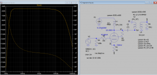
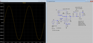
I haven't had a chance to measure the inductance yet (necessary gear is with a friend), but what I have done is checked the frequency response with different loads.
A 300 ohm dummy load showed no change in the spectrum from 32 ohm. I then tried 600 ohms. Still no change. Lastly, out of curiosity, I stuck an 8k resistor in. No change!
Does this mean the problem lies elsewhere? 😕
The signal transformer is still low ohmage by definition of its primary winding. This couldn't be changed by simple change of load impedances. It has low turns windings and will not convert to a high impedance transformer.
But I don't get the idea how this can work sufficiently anyway. Maybe try to contact Hagermann, this wouldn't be a multi million dollar company.
But I don't get the idea how this can work sufficiently anyway. Maybe try to contact Hagermann, this wouldn't be a multi million dollar company.
DontHertzme,
In order to check the frequency response of an output transformer:
Start with the output tube plate resistance, rp, in the mode you will use it (Pentode/Beam Power; Ultra Linear, or Triode/Triode wired).
Calculate: rp Ohms, Minus the output impedance of your signal generator = R series Ohms.
Example: rp = 1700 Ohms, generator output impedance 50 Ohms. 1700 -50 = R series = 1650 Ohms
Put a resistor, R Ohms, in series with the generator output.
Connect the generator in series with R Ohms to the output transformer primary.
Connect the load resistor across the output transformer secondary.
Now, measure the frequency at many frequencies out of the generator.
Calculate the frequency response.
If you connect the generator Ohms and series resistor R Ohms to the primary, that is less than the tube rp, you will not get the correct frequency response, it will be better than when driven by that output tube's rp.
If you use a really low impedance to drive the primary, it will not make much difference in frequency response when you load the secondary with 32, 300, or 600 Ohms.
Hopefully, you will now find the true frequency response of your output transformer.
Last edited:
From an OTL and 32ohm perspective:
* impedance affects frequency response, so adding tubes in parallel will lower the output impedance. With an OT in the way I suspect you’d need to look at that and the impedance it would support.
* capacitance in the design along with resistances n the design acts like a filter (including Miller capacitance). The cap change will also change the transient response if you look at a square wave.
* Syphoning gain into negative feedback is a quick way without messing up - in certain circumstances the NFB also makes the amp cope with low impedance by causing it to increase gain - not sure what effect that would have on the output transformer.
NickKuK,
How did we get from the discussion of an SE amplifier with an output transfomer, to an OTL amplifier?
Which Post # in this thread?
How did we get from the discussion of an SE amplifier with an output transfomer, to an OTL amplifier?
Which Post # in this thread?
Things get stranger.
I haven't had a chance to measure the inductance yet (necessary gear is with a friend), but what I have done is checked the frequency response with different loads.
A 300 ohm dummy load showed no change in the spectrum from 32 ohm. I then tried 600 ohms. Still no change. Lastly, out of curiosity, I stuck an 8k resistor in. No change!
Does this mean the problem lies elsewhere? 😕
If the inductance is too low you can't do anything to correct the bandwidth 😀 , otherwise they would done it a long time ago , manipulating load is simple ... Only more negative feedback could made it more linear , or of course changing the circuit for a tube with a much lower Ra and so on .
As I said the inductance is in parallel with Ra , if it's small will shunt it more and more at low frequency , very simple ... No normal Ra for the tube = low power for those frequencies , like in your graph .
This is why any transformer will have a roll-off at low frequency , inductance can't be made infinite .
Last edited:
NickKuK,
How did we get from the discussion of an SE amplifier with an output transfomer, to an OTL amplifier?
Which Post # in this thread?
Ease up 🙂 Just making the point my experiences are not OT based but some suggestions cross the divide.
I don't know if this is the case but usually they omit the power level for advertized bandwidth , so it could be very low 😀 or just invented theoretically not measured at all .
Last edited:
Specifications
Sensitivity 3.5Vrms
Input Impedance 50k ohm
Output Impedance 5/35 ohm (LO/HI)
Bandwidth 10Hz to 150kHz
Output Power 350mW @ 32 ohm
Gain 6dB (HI)
Output Voltage 7Vrms @ 1% distortion
Size 6 x 10 x 3.5 inches
Power 15Vdc @ 1.35A
I think spec is clear enough and a headphone amp with no bass will quickly get a bad rap these days.
Attachments
- Home
- Amplifiers
- Tubes / Valves
- Poor frequency response EL84 parafeed HPA