Bandwidth 10Hz to 150kHz
Output Power 350mW @ 32 ohm
Like I said , it is not explicit stated that the bandwidth is at the rated output power , you could think so but also could be measliding .
And not specified at -3dB or whatever value , could be anything
Output Power 350mW @ 32 ohm
Like I said , it is not explicit stated that the bandwidth is at the rated output power , you could think so but also could be measliding .
And not specified at -3dB or whatever value , could be anything
Last edited:
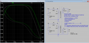
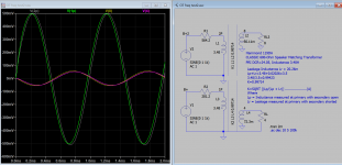
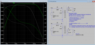
Here is the sims showing the shift of frequency response of the OT with different load and impedance compared with intended load and impedance. I hope this helps to explain the differences.
Attachments
What I think I am observing in this thread, is a few amplifiers that work good with certain headphones.
Matching a particular headphone impedance, and particular headphone sensitivity,
requires both the proper selection of the output tube, and the proper output transformer.
With many headphones of from 32 Ohms up to 600 Ohms, and widely different sensitivity of the different headphones, requires one of two things:
Either a complete match of tube, transformer, and headphone,
Or, a brute force design that can drive all headphones satisfactorily.
Mixing and matching of two or more headphone amplifier circuits, and mixing and matching of the same parts / different parts will not work.
Start with the exact requirements of the exact headphones, or else the performance will be hit and miss, especially if it is on a budget.
Just my opinion.
There’s an interesting design over at tubecad, a buffer with two impedance values.
Variations on a headphone Amplifier
And to a lesser extent:
Variations on a headphone Amplifier
Last edited:
NickKuK,
I should have said that without multiple taps, or extremely low output impedance, no one amplifier will optimally drive multiple impedance headphones of extremely different impedances.
That first and second links, are great starters. Unfortunately, the first one shows an OTL amp that puts 140VDC onto the headphones.
Those circuits are incomplete, and unsafe for the average person who may not know about safety implications.
Simplified circuits are just that . . . too simple.
"You should make things as simple as possible, but no simpler". Albert Einstein.
All Generalizations Have Exceptions.
Last edited:
NickKuK,
I should have said that without multiple taps, or extremely low output impedance, no one amplifier will optimally drive multiple impedance headphones of extremely different impedances.
That first and second links, are great starters. Unfortunately, the first one shows an OTL amp that puts 140VDC onto the headphones.
Those circuits are incomplete, and unsafe for the average person who may not know about safety implications.
Simplified circuits are just that . . . too simple.
"You should make things as simple as possible, but no simpler". Albert Einstein.
All Generalizations Have Exceptions.
It was more the "IMC" 10V buffer further down in the first link I was thinking of 🙂 the second being for electrostat. It's possible to create a opamp with tubes but at the same time it's complicating, where simply designing for your headphones is key.
It did occur to me to suggest that low impedance = higher power = larger transformer flux required = larger driving stage, which then means changes that slowly end up redesigning the amp (paralleled tubes, mean selecting the right transconductance, adjusting for larger miller capacitance etc).
So I agree, in the world of simplicity - keeping your design 'pure' for the intended impedance range.
Just skipping to solid state for a second - the Chord Mojo has an output impedance of 75milli-ohms with a 5V max output, it will output 4.2V (35mW) with 600ohm and 2.4V (720mW) into 8ohm it uses three dual packages per channel. There's no statement on the change of frequency response between the two.
My point here is you can see the difference in requirements and expecting that from a single tube back end isn't going to result in a simple design.
Last edited:
If the value for leakage inductance is correct in the simulation , about 20mH , then that transformer is very bad , not interleaved .
So you dont have low frequency and high frequency 😀 . This is hopeless , even by hand you could made a better transformer for audio .
So you dont have low frequency and high frequency 😀 . This is hopeless , even by hand you could made a better transformer for audio .
Here is the sims ....
BTW where does this term come from?
K= SQRT( Lp/(Lp+Lsp) )?
Verified K:
{Leakage = (1-k^2)*L(pri)} ........................(B)
Lr=(1-0.99429)*3.48=0.020
Coupling factor "k" in LTspice..meaning? | Forum for Electronics
It's found LTspice tutorial and elsewhere.
{Leakage = (1-k^2)*L(pri)} ........................(B)
Lr=(1-0.99429)*3.48=0.020
Coupling factor "k" in LTspice..meaning? | Forum for Electronics
It's found LTspice tutorial and elsewhere.
The coupling cap value for 30H and a 600 ohm OPT would be about 150uF.
The Hammond transformer that's chosen is a horrible choice. Get a little 5K-10K Edcor WSM line matcher instead. There will be a limit to how high the reflected impedance could possibly be with that Hammond OPT, and it won't ever be high enough.
The Hammond transformer that's chosen is a horrible choice. Get a little 5K-10K Edcor WSM line matcher instead. There will be a limit to how high the reflected impedance could possibly be with that Hammond OPT, and it won't ever be high enough.
{Leakage = (1-k^2)*L(pri)}
Lsp = (1-k^2)*Lp
Lsp/Lp = 1-k^2
k^2 = 1-(Lsp/Lp)
k = SQRT( 1-(Lsp/Lp) )
or
k = SQRT( (Lp-Lsp)/Lp )
"BTW where does this term come from?
K= SQRT( Lp/(Lp+Lsp) )? "
Thank you for remind me. k = SQRT( (Lp-Lsp)/Lp ) is what I seen in LT tutorial before, can you verify?
Phew, lots to take in here. Thank you everyone 😀

Brilliant, thank you so much! I'll put the numbers together this week when I have a gap. This is really useful.In order to check the frequency response of an output transformer:
. . .
Hopefully, you will now find the true frequency response of your output transformer.
And transformers would be much smaller and cheaper 🙂.If the inductance is too low you can't do anything to correct the bandwidth 😀 , otherwise they would done it a long time ago
Yup. The moment I put the headphones on it was immediately apparent that all was not well. *Not* subtle.I think spec is clear enough and a headphone amp with no bass will quickly get a bad rap these days.
At this point I'd be really happy with useable 30HzThere are no miracles.
Frequency Response 30 Hz. - 20 kHz. +/- 1dB
That's also very useful, thank you! How did you obtain the detailed specifications of the 119DA? The inductance etc. aren't on the data sheet Hammond provide.Here is the sims showing the shift of frequency response of the OT with different load and impedance compared with intended load and impedance. I hope this helps to explain the differences.
I came across those in my Googling too. Interesting reading.There’s an interesting design over at tubecad, a buffer with two impedance values.
Variations on a headphone Amplifier
And to a lesser extent:
Variations on a headphone Amplifier
So I'm discovering, the hard way 😀! I had figured that the original design would be sufficient, given what I'd read about it.My point here is you can see the difference in requirements and expecting that from a single tube back end isn't going to result in a simple design.
There seem to be no issues with the high frequencies. It's near-flat 1kHz to 20kHz. And when listening the high end sounds fine. After all this I may just look into winding my own transformers. I found a nice Arduino project that controls a motor and counts the turns in case you get hypnotised 😉.So you dont have low frequency and high frequency 😀 . This is hopeless , even by hand you could made a better transformer for audio .
I currently have 50uF in there. I'll add another 100uF and have a look at the response. I'm going to have new OPTs made this week. Which of the Edcor WSMs would you suggest? The lowest impedance secondary I see is on the 8.2:1 10k:150ohm unit.The coupling cap value for 30H and a 600 ohm OPT would be about 150uF.
The Hammond transformer that's chosen is a horrible choice. Get a little 5K-10K Edcor WSM line matcher instead. There will be a limit to how high the reflected impedance could possibly be with that Hammond OPT, and it won't ever be high enough.
Thank you for remind me. k = SQRT( (Lp-Lsp)/Lp ) is what I seen in LT tutorial before, can you verify?
Correct.
p.s.
Interestingly in my practice (given -good- transformers, the manufacturer gave it the parameters -L, R, C, Lsp, bandwidth etc.-) the SQRT function gives "too good" HF behaviour compared to measuring of transformers (done by me, or even by manufacturer).
Attachments
I currently have 50uF in there. I'll add another 100uF and have a look at the response. I'm going to have new OPTs made this week. Which of the Edcor WSMs would you suggest? The lowest impedance secondary I see is on the 8.2:1 10k:150ohm unit.
Since this is a spud amp, 10K:600 is probably a reasonable choice. A 1uF cap between your 30H choke and this transformer would probably be OK.
I still feel there is something being missed. It is possible to regap the 157G for higher inductance, but the 119DA is the weakest point. Puzzling.
157G has 30H/40mA , you can't do much since will saturate the core . The DC is passing through .
But the output transformer doesn't need air gap so you could dramatically increase the inductance , maybe from 3,5H to comparable value as the choke . Or with a good transformer you could have really high inductance .
But the output transformer doesn't need air gap so you could dramatically increase the inductance , maybe from 3,5H to comparable value as the choke . Or with a good transformer you could have really high inductance .
Last edited:
I see. Perhaps the 119DA got an exotic core upgrade or something like that. Deducing from the spec, transformer primary should be > 4k.
So the OPT primary measures at a puny 800mH, open circuit. Waaay too low 😱. Going to experiment with some feedback while I wait for new transformers.
Applying feedback helped somewhat, at the cost of gain, which this circuit can't spare.
The solution was indeed a better output transformer - 5k with 150 and 30ohm secondaries worked out very well. Definitely not "hifi" but a fun little project 🙂.
The solution was indeed a better output transformer - 5k with 150 and 30ohm secondaries worked out very well. Definitely not "hifi" but a fun little project 🙂.
- Home
- Amplifiers
- Tubes / Valves
- Poor frequency response EL84 parafeed HPA