2wo said:Hi there,
Haveing just figured this out just now...
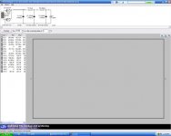
once you have your pic, save it to your desktop (so you cand find it again) At the bottom of the reply screen there is an 'attach file' section click on the 'browse' button, then find your photo and click on it. that should do it. Like this
That's what I thought but I can't see the image when I check preview. Here is an attempt to attach a photo:
Steve A
Attachments
SteveA said:I can't see the image when I check preview
That is a bug in the board software -- don't use preview...
dave
2wo said:The power supply is from parts on hand a pair of Allied 250V 25ma transformers full wave CT.
Does your trafos output 250v - 0 - 250v or 125v - 0 - 125v?
2wo said:No there is just one primary I double checked the in and out voltages, there is ~250VAC at the output which led to the thought that maybe one of the diodes is bad or not connected properly and it’s half waving but no it’s not . John
If you check from "in" to "out" you should see 500v for a CT. You should see 250 from CT to either end.
It's unlikely to be the caps. Check the DC voltages at each point after the rectifier. Then start disconnecting components from the output end. This will be easy to diagnose.
Sheldon
To SteveA,
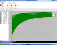
Remember when you use psud2, you need to set a reporting delay. I use 30s by default . This lets things settle down to a steady state voltage before reporting.
All in all this looks pretty close, I changed R2 to 2k and got 235V. This is close enough to build. A sim is not nearly perfect. Just see my last post or two. Don’t tear your hair out trying get spot on. This is tubes after all. 10% would be 198-242.
If you are building with the power supply PCB, do not add the diodes. Sim it for yourself and see what happens. (Just a change to a SS full wave bridge is close enough for demo proposes) …John
2wo said:Remember when you use psud2, you need to set a reporting delay. I use 30s by default . This lets things settle down to a steady state voltage before reporting.
That's kind of dangerous advice to give. It's very easy to overlad a tube rectifier on startup.
No,
If you do not use a delay you will not get usable info.
What you can do is turn on warnings. This will tell you if you are overdriving your rectifier. On the other hand it will flag if you exceed anything, by even one cycle, so you still need to use your judgment.
If you keep your input cap to a reasonable value and keep an eye on your currents. You should be good to go
Watch out for brain farts, Look above. I was modeling my Aikido supply and forgot that a quirk of psud2, for a full wave rectifier, the transformer voltage you enter is from one leg to the CT not the rated voltage.
SteveA take note of this.
Remember this is a tool not an oracle...John
2wo (and anyone else)-
2wo quote:If you are building with the power supply PCB, do not add the diodes. Sim it for yourself and see what happens. (Just a change to a SS full wave bridge is close enough for demo proposes) …John
Do you mean don't include the diodes in the PSU sim or leave the diodes off the pcb (if off the pcb I don't understand). I used a 5 sec delay in my simulations.
The PSUD info Bas posted on page 21, was that intended to be the simulation corresponding to the PSU V1.0 from page 27 (I don't follow the 450R)? I am trying to understand C-R-C-R-C in terms of the components listed on the V1.0 schematic.
When I simulate (editing the PSUD simulation from page 21) using C1=1uF, R1=1k, C2=180uF=C3, R2=2k) I get 226V without getting the message: IFRM exceeded........ BTW, I would assume one should simulate to avoid this condition.
Thanks,
Steve
Hi Steve,
I am sorry I have given you bad information.
The supply you copied above, is a full wave. One diode or tube section, on either end of a center taped transformer, with the center tap as ground.
To model this in psud2, with a 250VCT (125-0-125 ) transformer you use 125 as your transformer voltage.
Bas’s supply is a hybrid full wave bridge . 2 tube sections and 2 diodes.
There isn’t one in psud2 so you model your supply with a tube bridge, then change it to SS bridge.
Your voltage will be somewhere in the middle. The difference is not huge and will give you an idea.
However this time we take the same 250VCT transformer, ignore the center tap and use 250 as the transformer voltage.
floating heaters
hi guys
i've read thru this thread a few times and still am a little unsure about floating heaters.
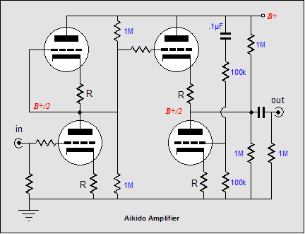
from the above schematic, cathode top section of first tube and cathode bottom section of first tube will operate at vastly different voltage.
if this is physically one tube, how do i float the cathode of the top section if the tube has a common heater?
thanks.
hi guys
i've read thru this thread a few times and still am a little unsure about floating heaters.
from the above schematic, cathode top section of first tube and cathode bottom section of first tube will operate at vastly different voltage.
if this is physically one tube, how do i float the cathode of the top section if the tube has a common heater?
thanks.
if this is physically one tube, how do i float the cathode of the top section if the tube has a common heater?
The answer you can’t .as you raise one half the other goes for the ride. This won’t do any harm, some say it’s a good thing. Just watch that you don’t bias up so high that you exceed the V hc for the lower half.
Another thing if you are using two identical tubes you can use one for the top and one for the bottom. And just bias the top. This really limits tube rolling though.
This brings another point. A 6sn7 has a V hc of +/- 200V. Most of the nine pin types that we are using are +/- 100V.
The 300k/100k divider gives me ~74V at 220V B+ and my highest cathode voltage is ~118V and lowest is ~ 1.5. So I am good to go.
But something to consider if using a different B+…John
2wo said:
The answer you can’t .as you raise one half the other goes for the ride. This won’t do any harm, some say it’s a good thing. Just watch that you don’t bias up so high that you exceed the V hc for the lower half.
Another thing if you are using two identical tubes you can use one for the top and one for the bottom. And just bias the top. This really limits tube rolling though.
This brings another point. A 6sn7 has a V hc of +/- 200V. Most of the nine pin types that we are using are +/- 100V.
thanks for the reply john.
i am under the impression that it cannot be done as well.
i've considered using same tube types so that both sections of one tube can be used for top and another tube for bottom. that way, i can raise the heater supplies for each tube correctly.
like you mentioned, it really limits the tube rolling... which brings the question of whether it is worth it to raise the heaters to the table.
Hi there I dont want to give the wrong impression.
Biasing both halfs of the tube (in this case ~75v) will work just fine, there is no harm in raising the lower tube...John
Biasing both halfs of the tube (in this case ~75v) will work just fine, there is no harm in raising the lower tube...John
Just make sure you are within the limits. The designer didn't worry about it. If you know something he doesn't, by all means redesign. Otherwise, it's just possible you might get the best results doing it his way. 😉
Sheldon
Sheldon
no worries, none given. 😉2wo said:Hi there I dont want to give the wrong impression.
sure, will check for that.Sheldon said:Just make sure you are within the limits. The designer didn't worry about it.
i'm just thinking of using some tubes that i have on hand, rather than go all out to procure other tubes for this project. i have some 6072, 12AU7, 5687 and 6SL7 that might be suitable.
was thinking of using 6072 + 6SL7 (5687 is too current hungry on the heaters).
Good to go.
6sl7-6sl7 might be fun.
That is one of the things I like about this pre, you can plug most anything in (ok, within reason) and play...John
6sl7-6sl7 might be fun.
That is one of the things I like about this pre, you can plug most anything in (ok, within reason) and play...John
more boards?
Bas
Do you have any Aikido linestage boards left? If so I would like to buy several more.
Thanks
Joe
Bas
Do you have any Aikido linestage boards left? If so I would like to buy several more.
Thanks
Joe
Hi Joe,
Yes, I have another stash..I got a couple extra ( and more) to send the the folks who's boards got lost.
Regards,
Bas
Yes, I have another stash..I got a couple extra ( and more) to send the the folks who's boards got lost.
Regards,
Bas
- Home
- Amplifiers
- Tubes / Valves
- Poll..anyone interested in an Aikido linestage PCB group buy?